
With Pictured Examples from the Joe Gruber Collection
Click on the picture above to see the large view
France
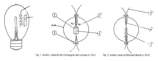
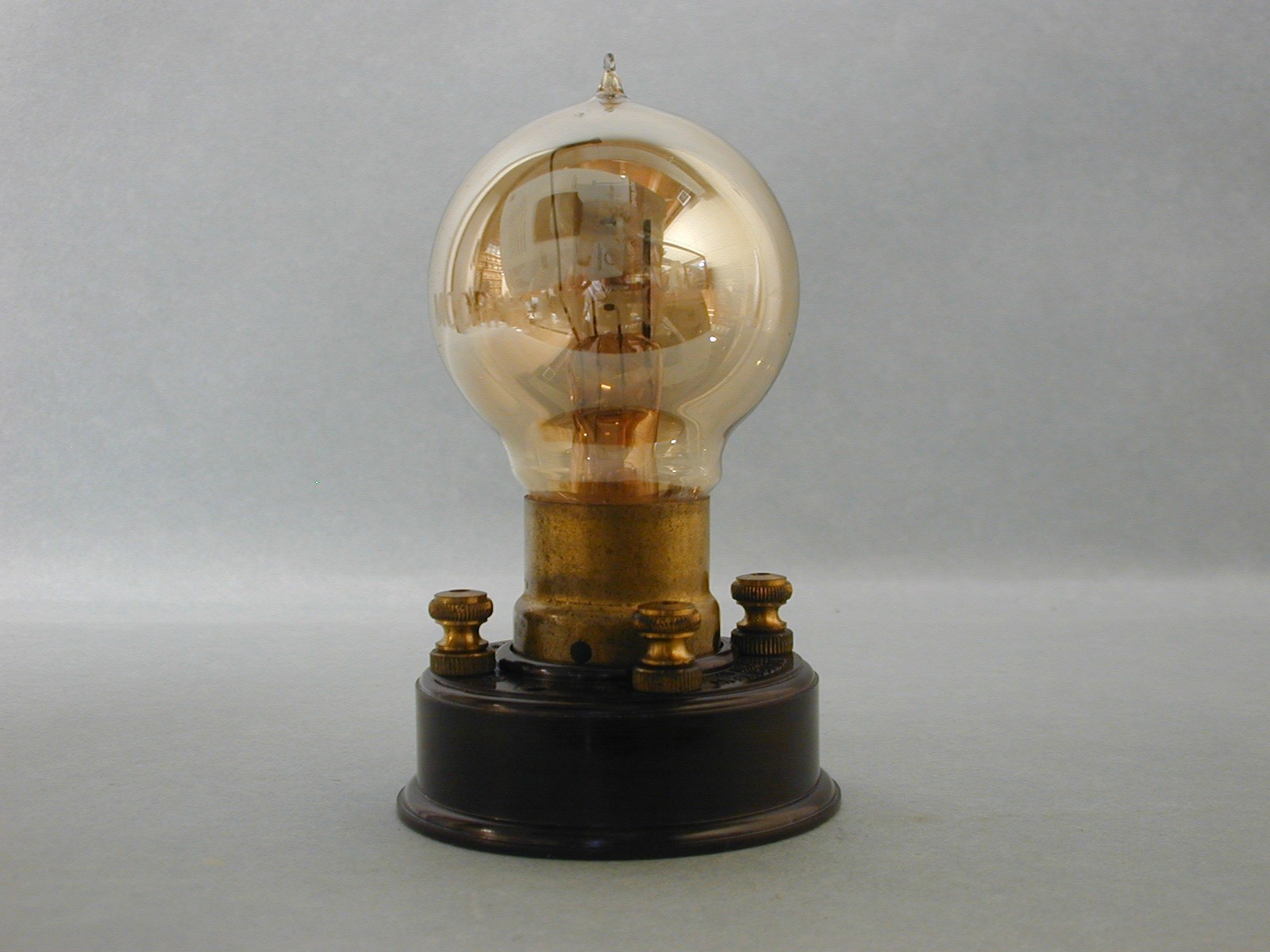
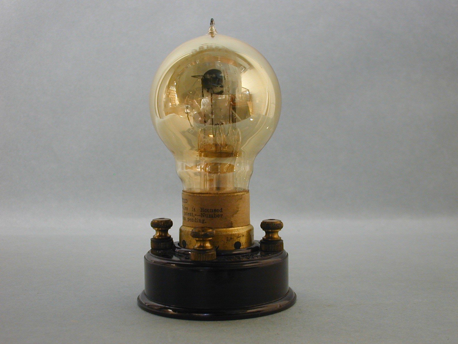
It did not escape the French military, with war imminent with Germany, that much work was going to be necessary in the area of telecommunications to speed up development and industrial output. To that end, the French government asked Colonel Gustave Ferrie, to be the technical director of the Télégraphie Militaire (Military Telegraphy) and charged him with the development of Telegraphie Sans Fil, (wireless telegraphy). Ferrie did much research on tube development in Germany and the US. By mid-1912, Ferrie had hired Henri Abraham, Gabriel Pelletier and Francois Peri, the tops in this field. In 1912, the French Navy asked Compagnie Des Lampes (Lamp Company) (Metal) to build a grid and a plate in a tube which looked much like a DeForest audion, shown in fig.1 and became known as the French audion. In 1913, this wireless telegraphy group, with the help of the Navy audion version, examples of the DeForest audion Ferrie and Henri Abraham acquired while visiting the US along with audions, purchased by Edouard Branly, with single and double plates along each side of the filament resulted in the spherical audion, shown in fig 2. The group, after war was declared with Germany in Aug. 1914, also persuaded Paul Pichon, a Frenchman, who had just returned from the US with new information about the DeForest audions, along with examples and who worked for the German company Telefunken, to turn over to them all he had learned. All of these configurations of audions were investigated but were dismissed for several reasons: They were hard to make, too fragile for military use, and were unstable as a detector, amplifier, and oscillator.
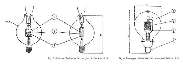
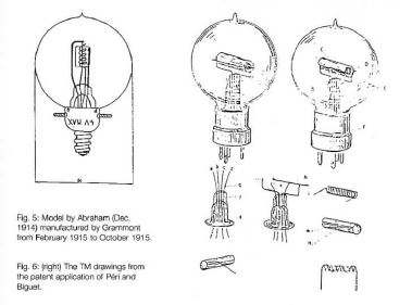
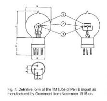
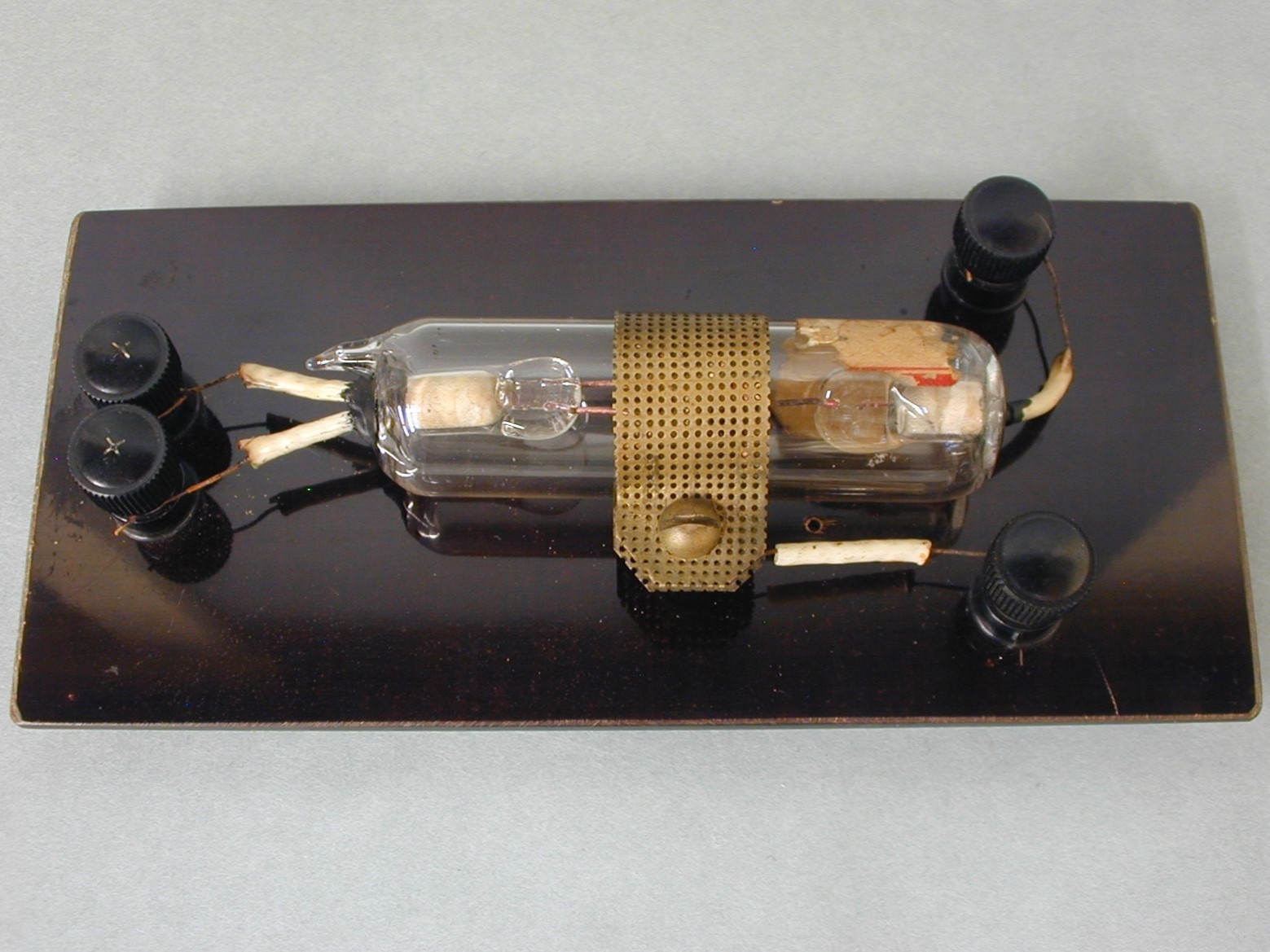
In October, 1914, Ferrie sent Abraham and Francois Peri to the Grammont light bulb factory in Lyon to make a better audions. Successive audions were made in small steps. Fig. 3 was a copy of the DeForest audion with the familiar double filament, single grid, and plate from Pichon. Then a double grid and plate supplied by Paul Pichon based on the Pliotron work of Irving Langmuir shown to the right in fig. 3. Fig. 4 shows a third prototype model that was too complex. They then made a still vertical structure with a cylindrical plate, a central wire for the filament and a spiral grid shown in fig. 5. These were made in insufficient numbers, most up to Oct., 1915 and shipped to the front but most did not survive. Ferrie complained about this to Peri and his partner Jacques Biguet, Abraham who had moved on, came up with a new ruggedized horizontal structure that proved to be very good. The patent application is shown in fig. 6. Fig. 7 shows the form and dimensions of what became the French type TM tube made by Grammont. Credit must be given to Abraham, also, besides helping in the designs, came up with a new process to heat up the inner structure, to drive off impurities, while the tube was being evacuated to a low degree of vacuum. This went on to set the standard for all vacuum tubes around the world to be made in this manner. Because France, Britan and the US used the new TM tubes in the fight, the need was great for more production. The final version had the new 4 pin base for ease of replacement, as can be seen in fig’s 6 and 7. Several companies besides Fotos Grammont made tubes for the war effort. Metal, Bigrille, and several others contributed, including those made in Britan and in the US. Grammont stopped making the TM brand following the war and started making tubes for use by the general public. The production of the TM was taken over by La Compagnie Générale des Lampes Métal, Radiotechnique, and La Société independent de TSF.
It cannot be over-looked that Ferrie, Abraham and others were conducting work on the Eiffel Tower for certain radio work. In doing so, they also helped in the first demonstration of Transatlantic Radio-Telephony in 1915. Fessenden had a system in place but negotiations with AT&T to sell his system fell apart. Carty and Arnold of AT&T overcame the problems and were able to send a message from the US Navy’s radio tower in Arlington, Virginia to the Eiffel tower. [10} [11}
See figures 1-7 and tube pictures below for the tubes used in WW1 along with a few post war Fotos Grammont tubes. See [1] in sources for the written updated year 2000 article by Fons Vanden Berghen of an earlier 1980 larger article called Grande Et Petite Historie- De La Lampe TM written in French by Robert Champeix. [4]
More history can be seen here: HIST


Description of figures 1-26 above:
Please click on all the pictures above for a larger view.
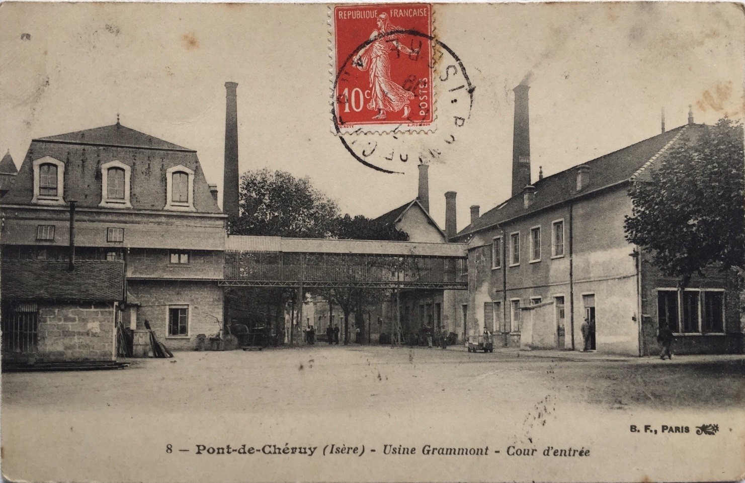
1&2: Figure 1, on the left, is what became the French audion. Figure 2 is an idea that came from Edourard Branly from a DeForest idea- 2 plates, each alongside both sides of the filament.
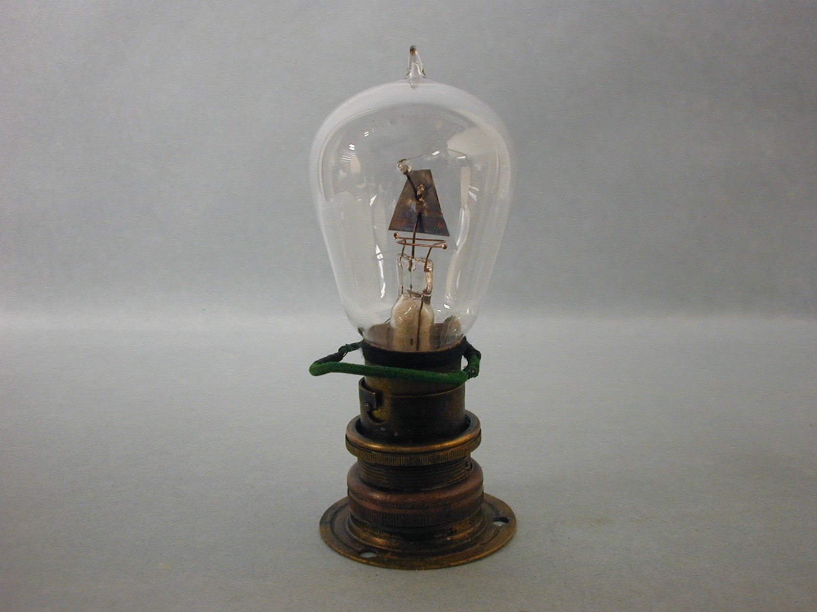
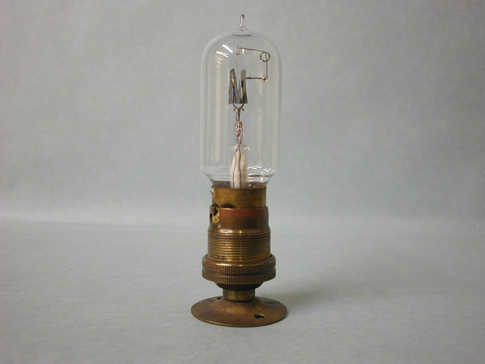
3 & 4. Figure 3, on the right, shows copies of US audion,s picked up by Paul Pichon while working for Telefunken. These were given to Ferrie at his insistence because of impending war with Germany. Figure 4 on the left is a prototype based on the Pliotron design by Irving Langmuir at G.E.
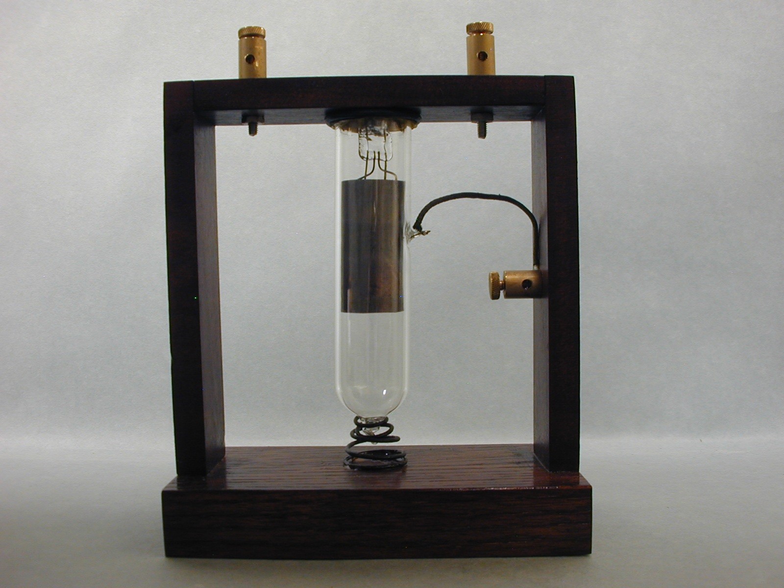
5 &6. Figure 5 tube on the left is an Abraham proposed type designed by with a still vertical structure. It had concentric electrodes: cylindrical anode, central wire filament and a spiral grid. Figure 6 shows the TM patent application drawings made by Peri and Biguet.
7. The final form of the TM tube after the patent application by Peri and Biguet made by Grammont. at their lamp factory.
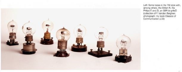
8. Various makers and forms of the TM tube, Philips E and British R that were all made very much like the French TM.
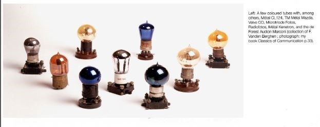
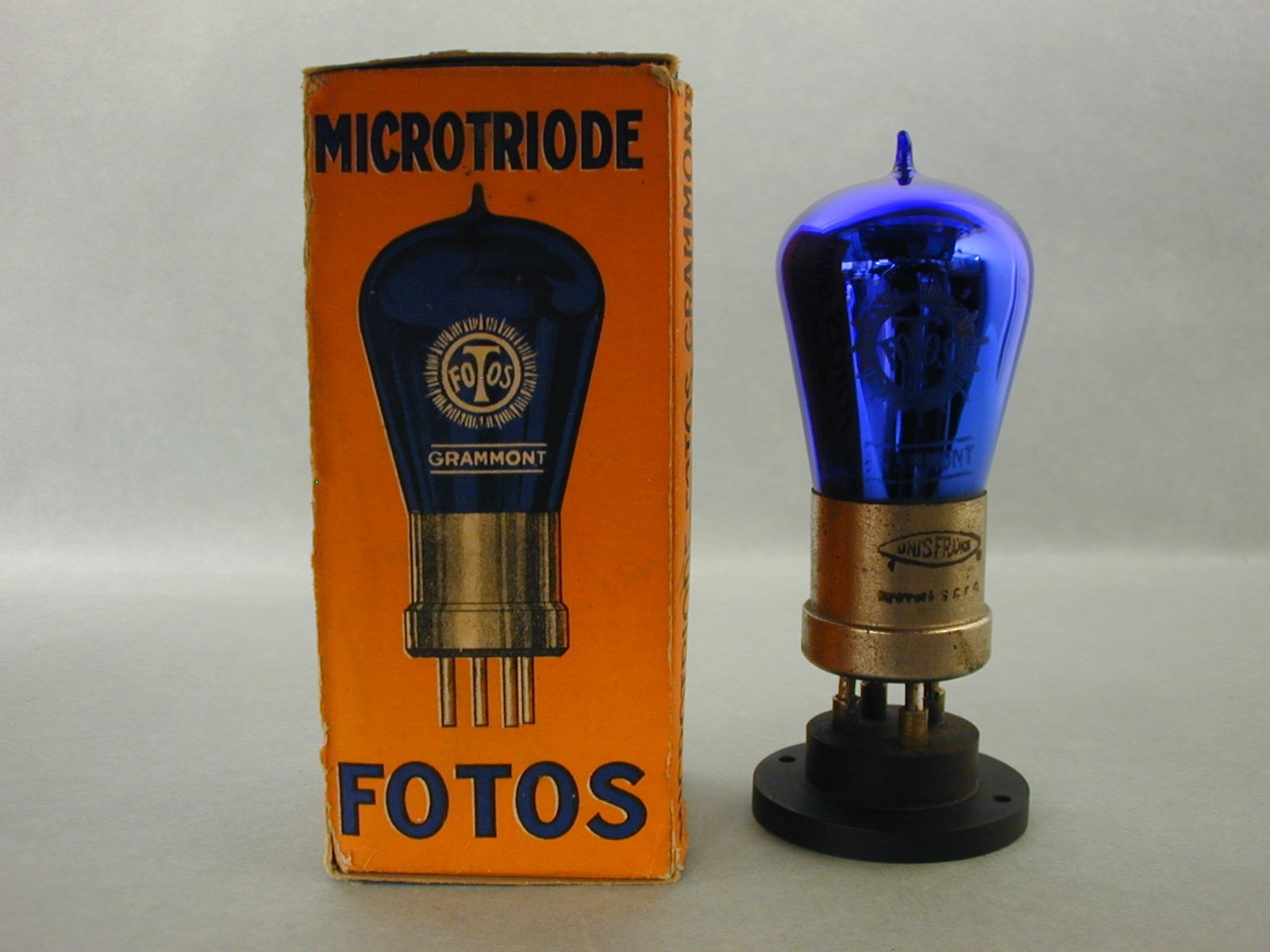
9. Various war and post war tubes by Moorhead, Metal, 2 forms of the Fotos Grammont Microtriodes and a few British tubes.
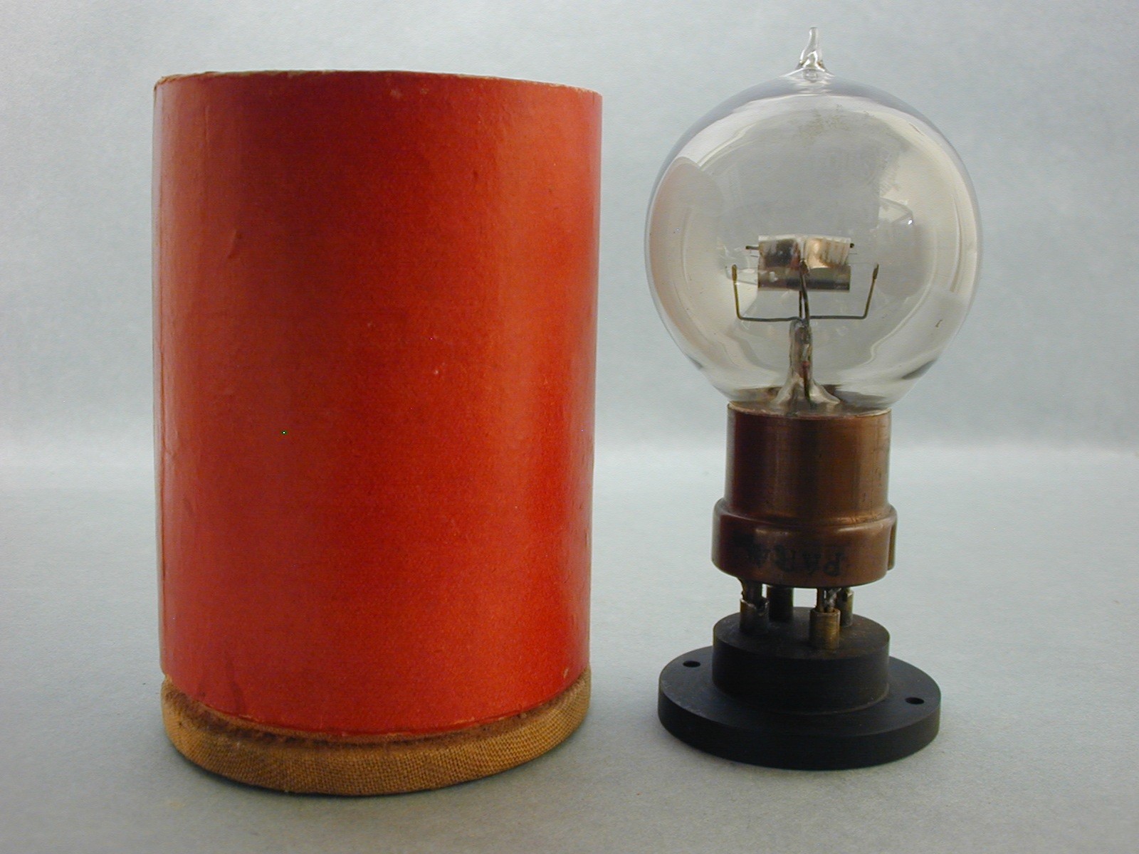
10. The French TM and shipping container that is exactly how the tube would have been sent to the front.
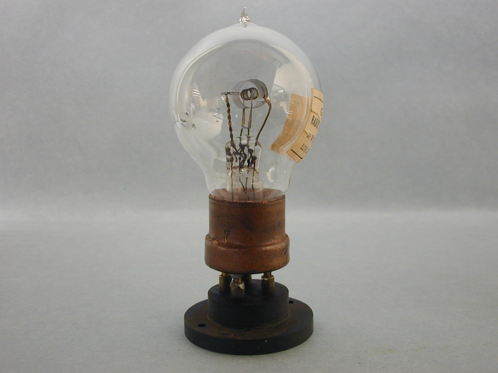
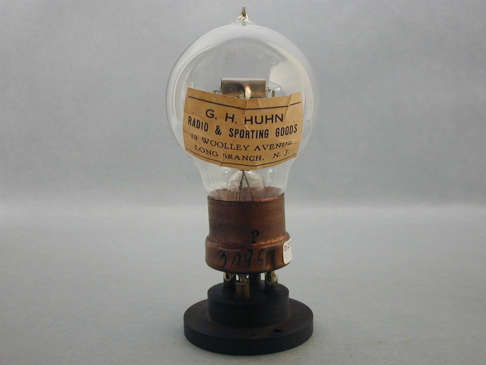
11 & 12. A French TM made by Metal. The paper tag on tube 12 shows it was a war surplus tube shipped to the US for sales after the war ended.
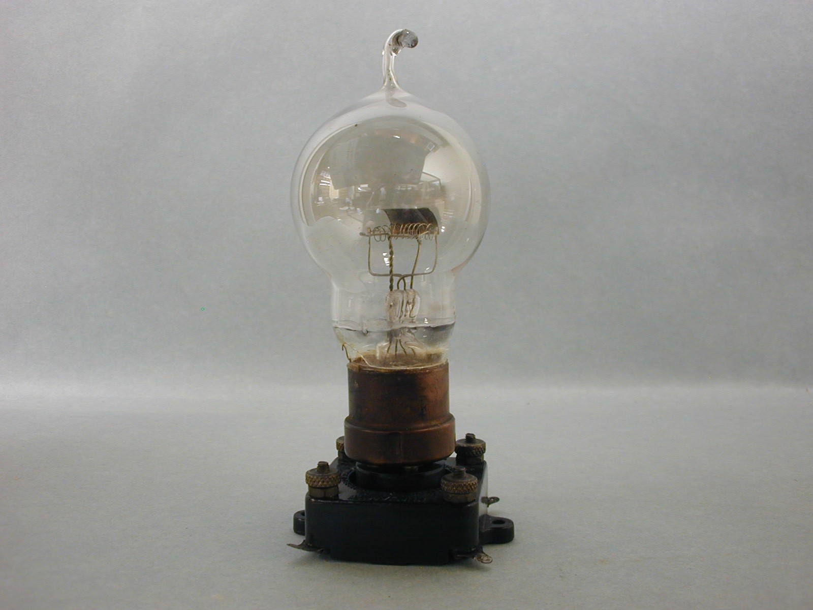
13. A repaired French TM made by Metal during the war. They were worth repairing in the beginning of the war because they were hard to make and were in short supply.
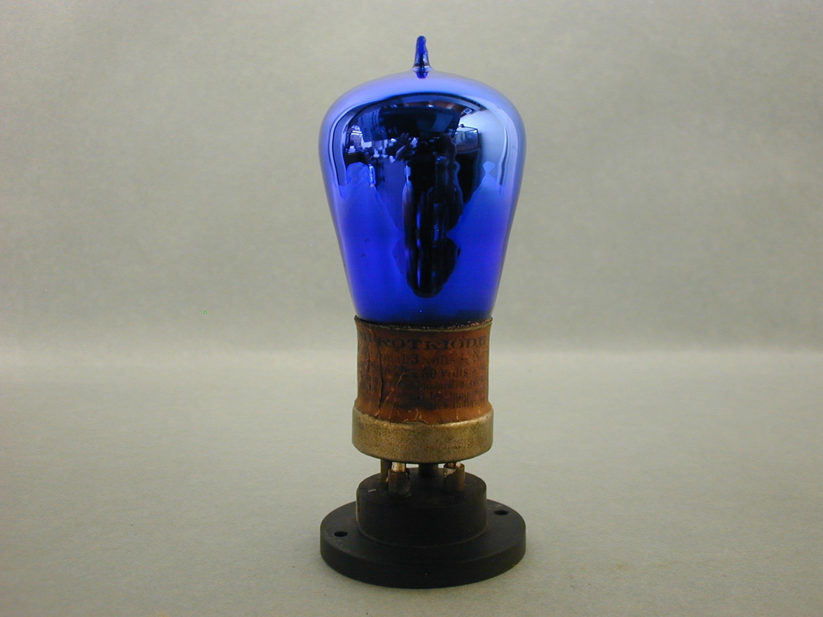
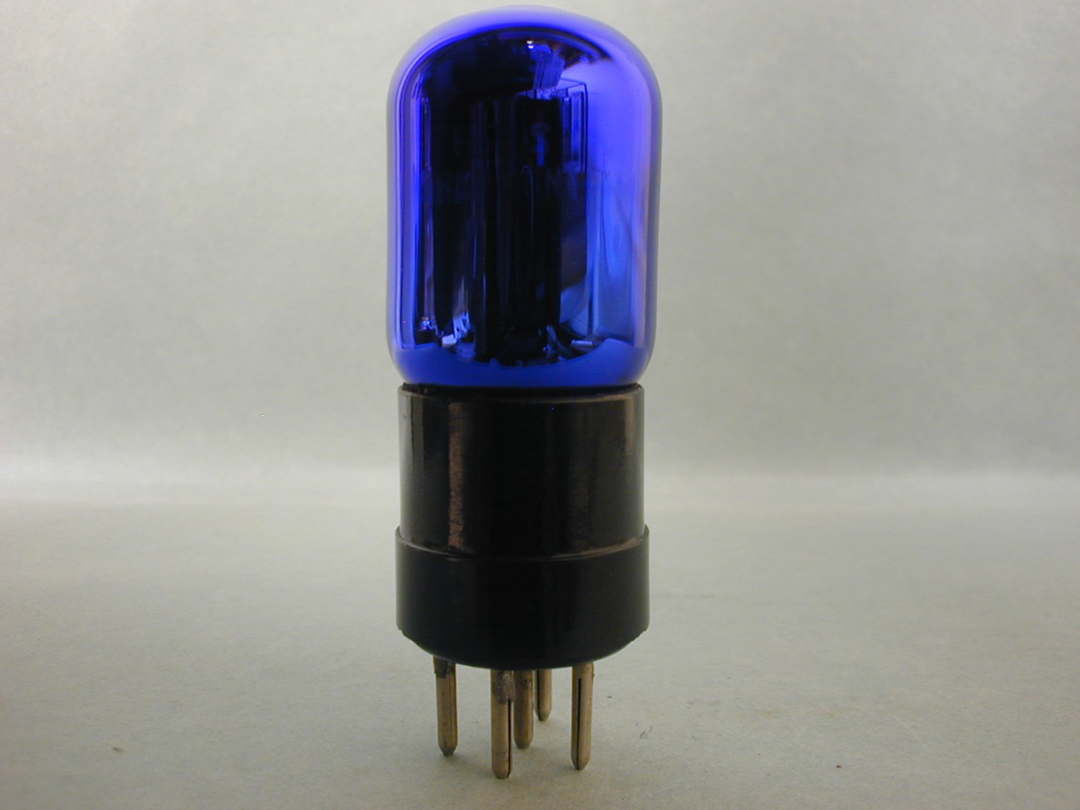
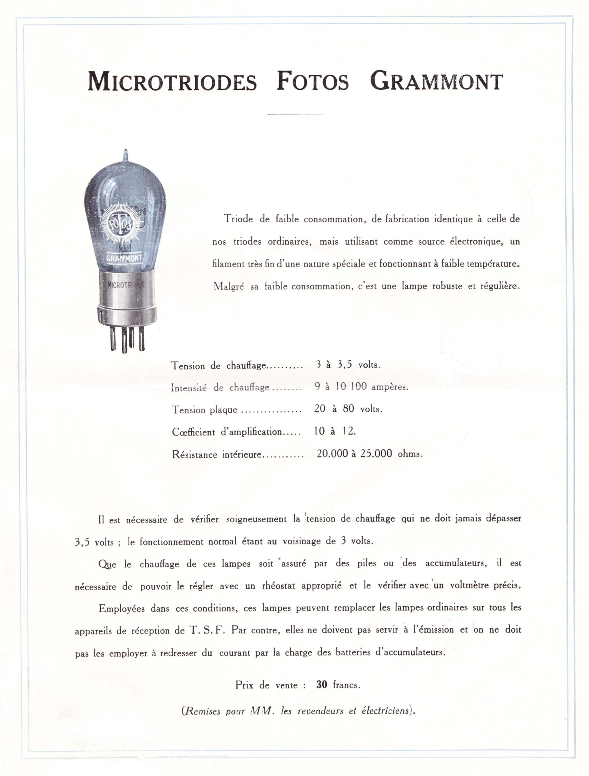
14. An earlier Fotos Grammont Microtriode is shown here but it was made before #15 as it has a paper tag with the specs instead of the later useage of ink. It appears as though it was easier to mark the base with ink rather than make a paper tag.
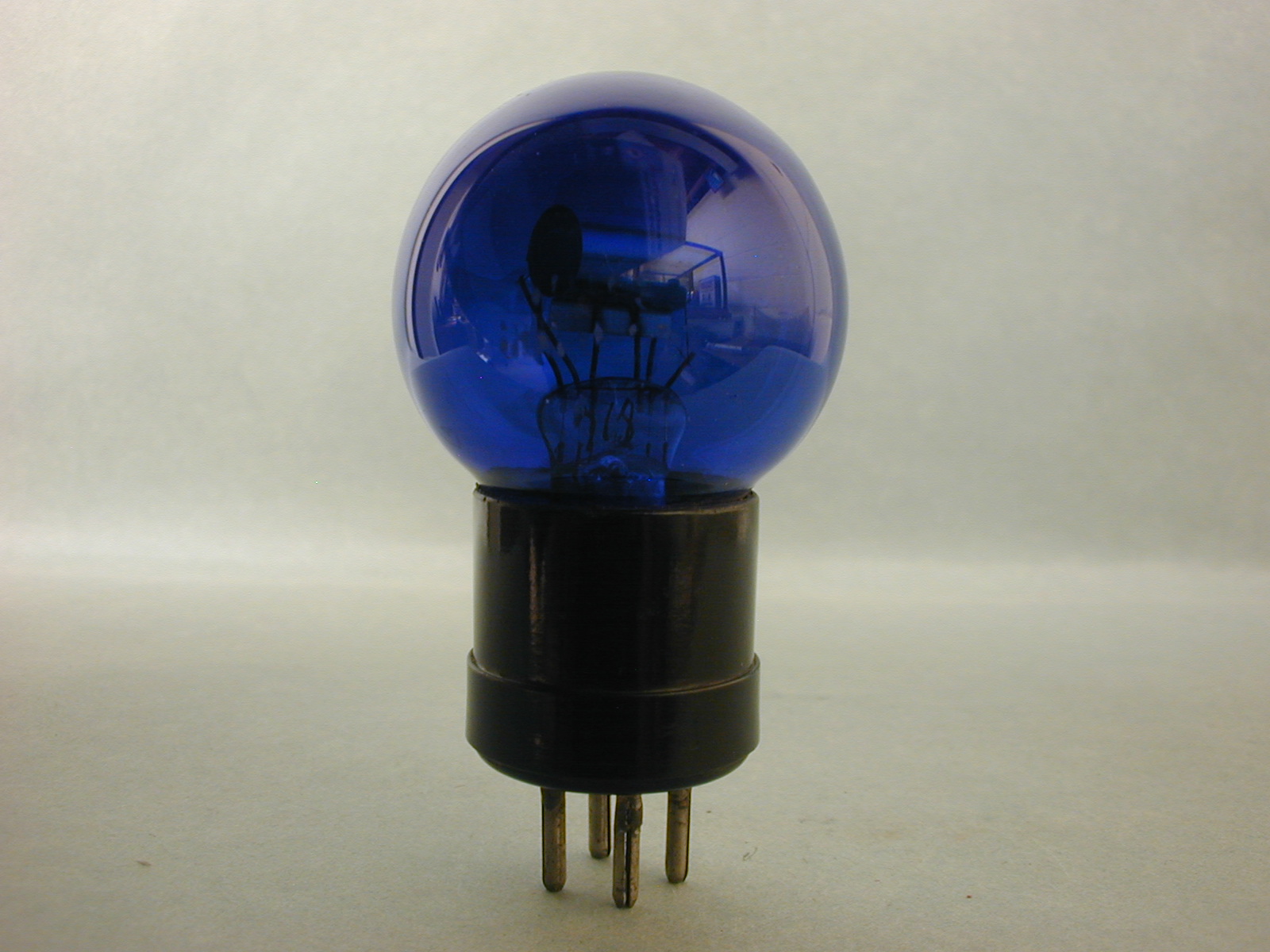
15. A post war Fotos Grammont Microtriode and shipping box from the 1923-1925 period. The specs are in ink on this tube which proves it was from a later period of manufacture. It is unknown why the bulbs were made blue but one can speculate that it kept the brightness down or perhaps to keep the internal structure hidden. Rene Lalique supplied the formula to make the blue glass bulbs or perhaps he made them himself. This is a known fact because in Lalique’s list of businesses he supplied, it listed Fotos Grammont.
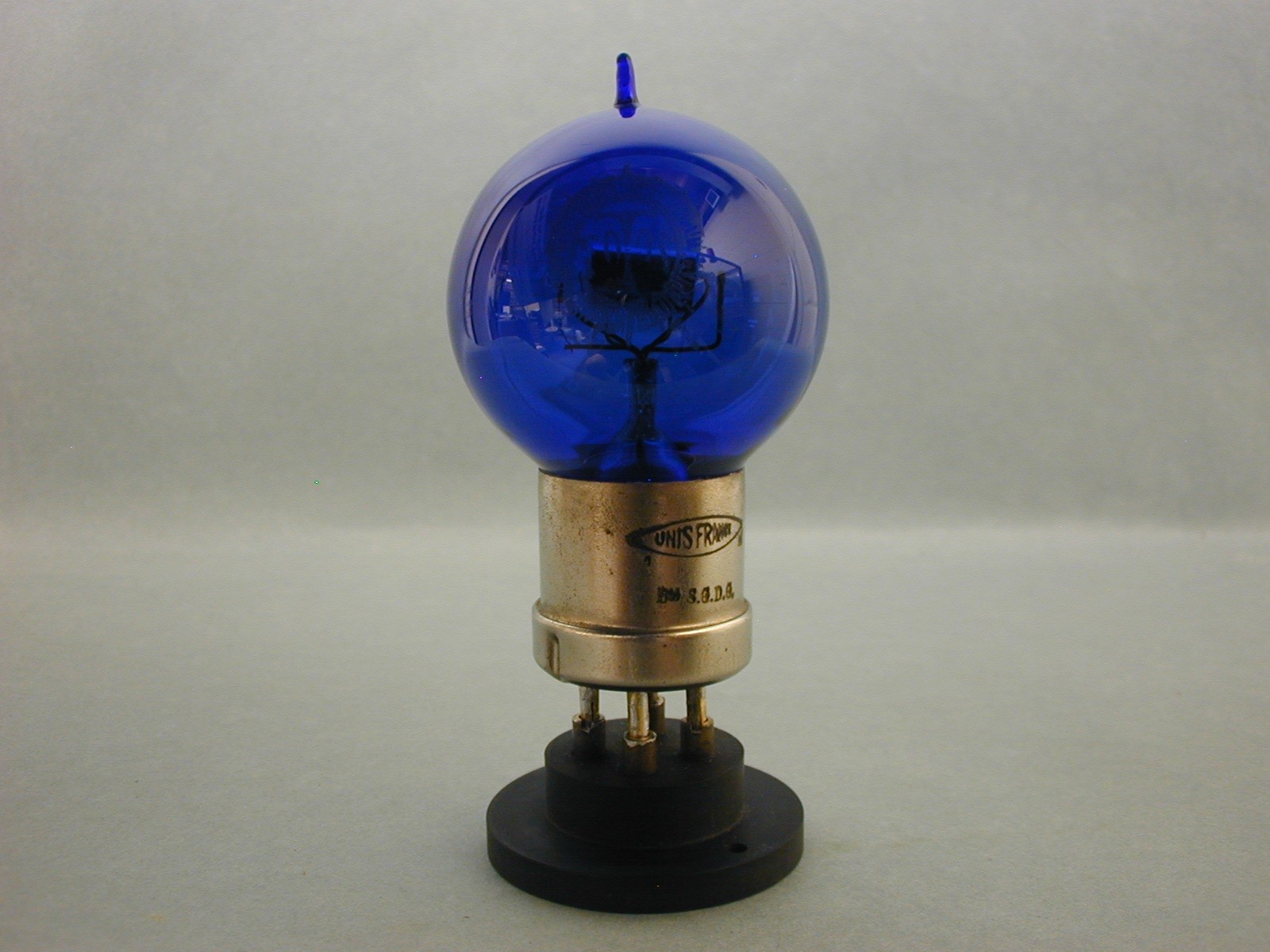
16. A later spherical form of the Microtriode is from 1924 or 25 but has the specs inked on the base. Hard to place a date on.
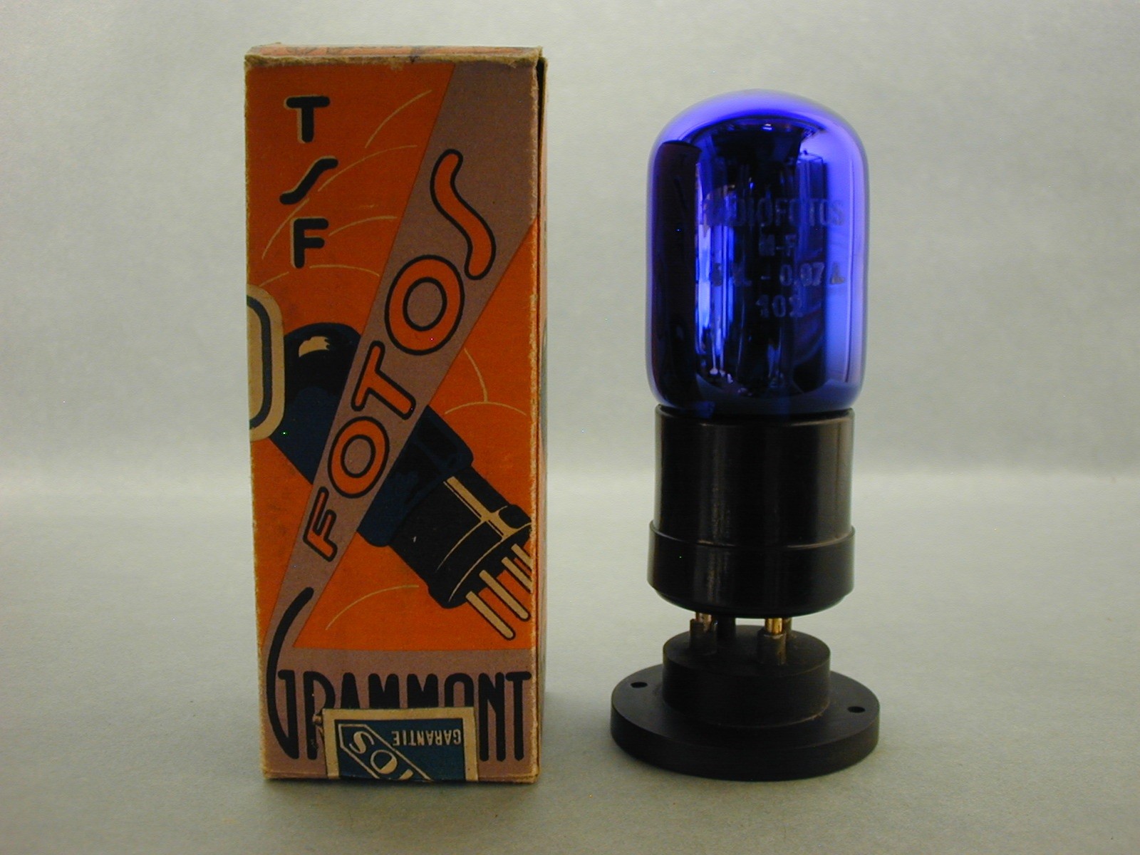
17. This Microtriode and box date from the 1925-28 period as the specs are on the box and it now has a bakelite base.
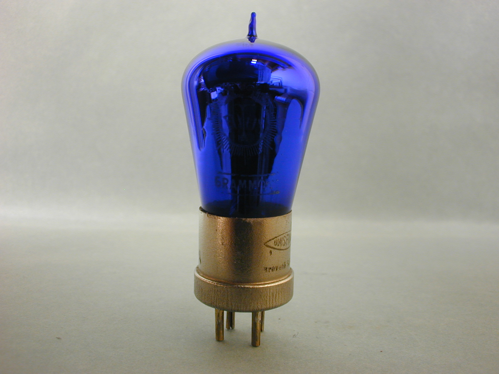
18. This is yet another Fotos Grammont Microtriode made after the paper tags used earlier have been replaced with an inked base. Has an odd 4 volt filament rating when most are 3 volt? Cannot account for this. A mistake?
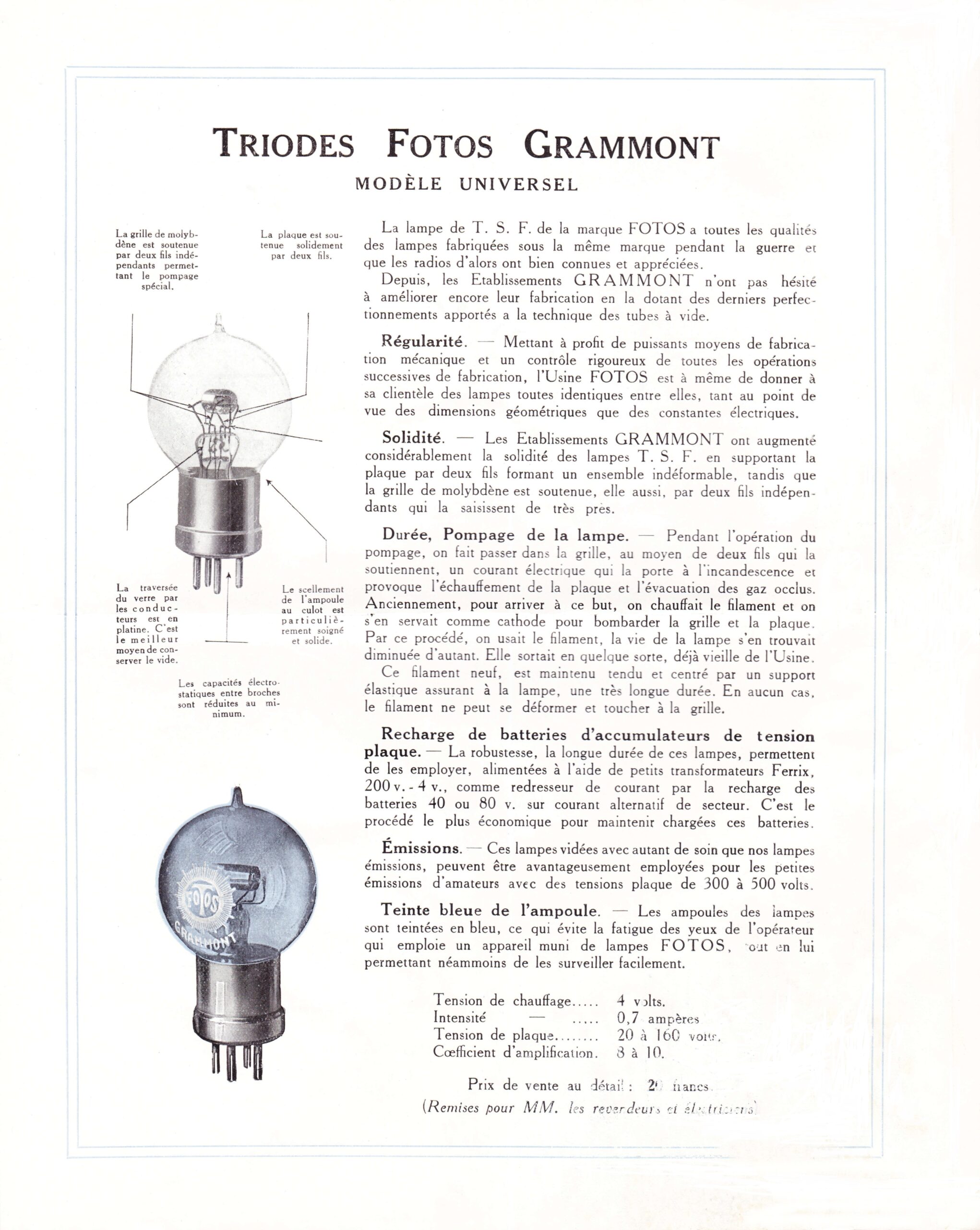
19. Fotos Grammont Universal Triode. 1925- 1927 period. It is also etched with an R for I presume Radiofotos.
20. This tube is a 40 volt Oscillatrice etched Brigille, who made tubes for Fotos Grammont. Again, from the later period, 1925-27.
21. Fig. 21 is different shaped 80 volt Oscillatrice made by Brigille for Fotos Grammont. It is also etched with a number 12 which seems to how Brigille ID’ed the tubes sent to Fotos.
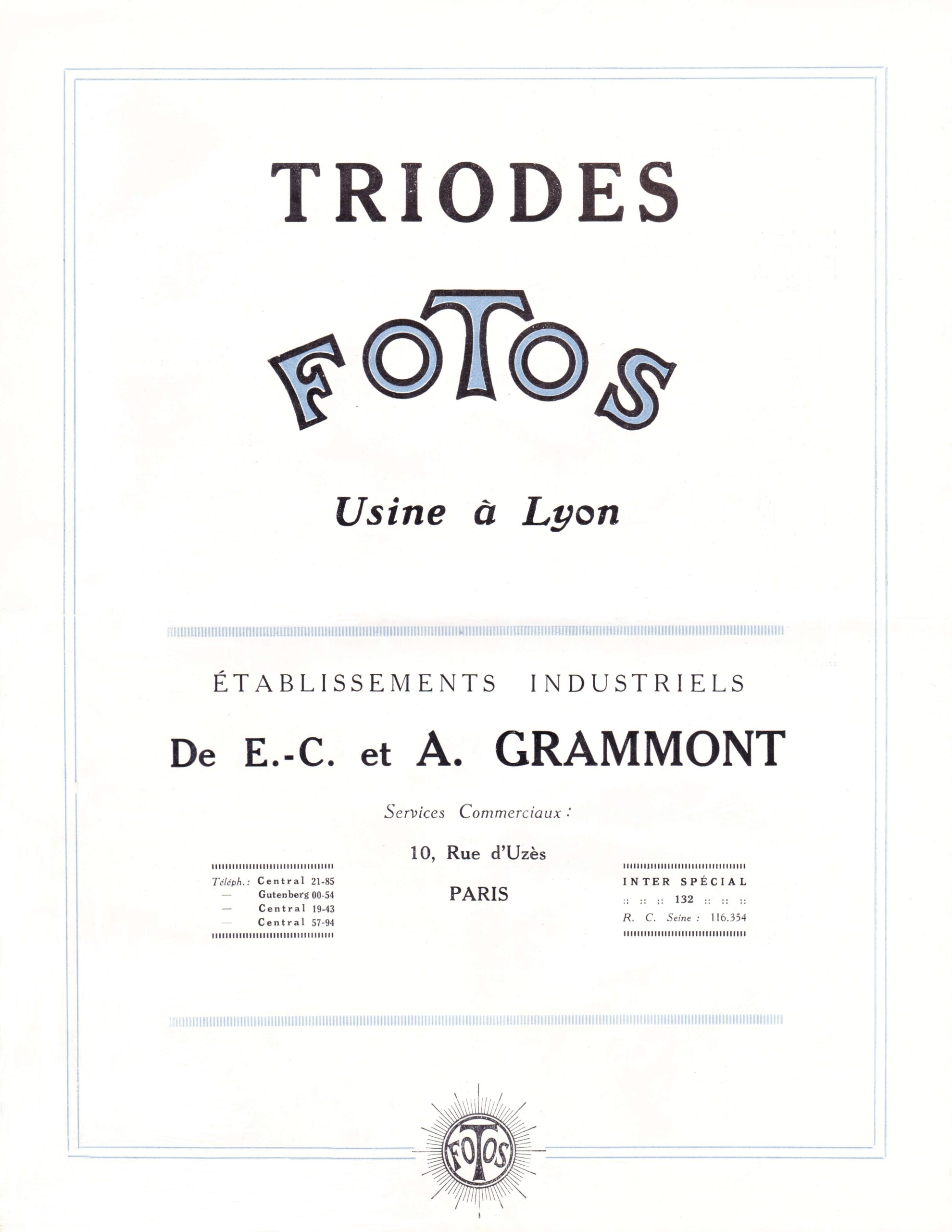
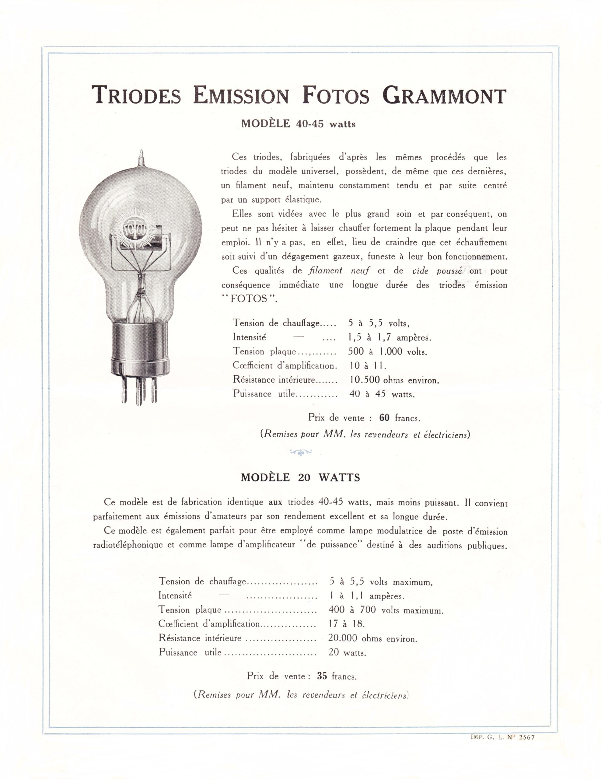
22 -22C. is a 4-page Fotos Grammont advertising catalog from the 1923-24 period.
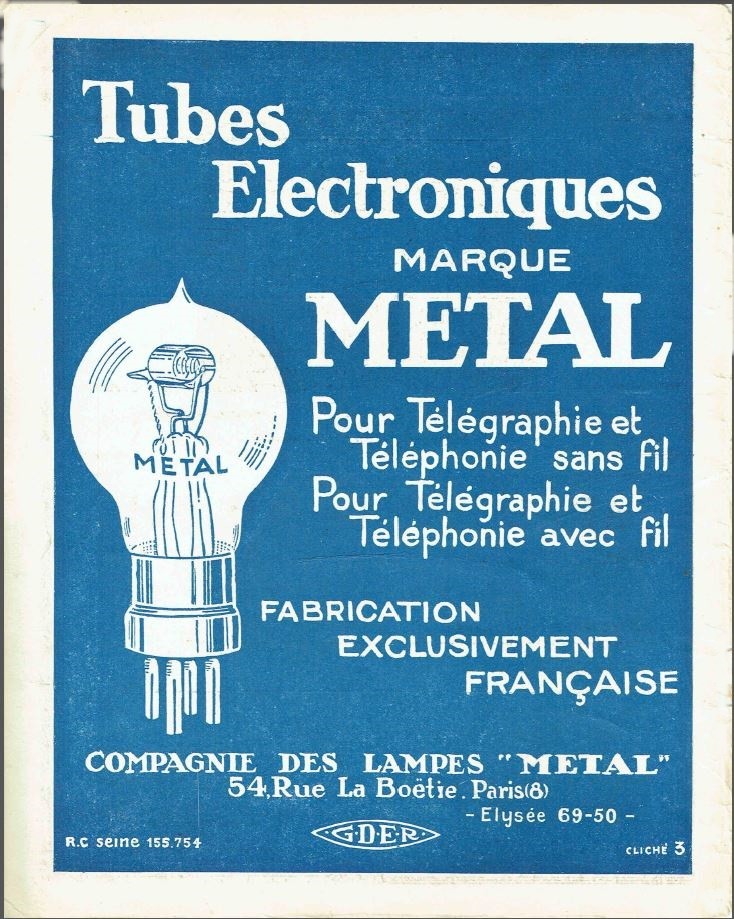
23. A Compagnie Des Lampes, (Lamp Company) otherwise known as Metal ad, for their TM tube.
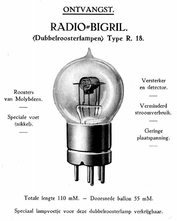
24. Bigrille is another TSF war time maker who supplied tubes for Fotos.
25. The Grammont lamp and tube factory in Lyon, France, near Paris.
26. Early stock certificate from Fotos Grammont.
Britain
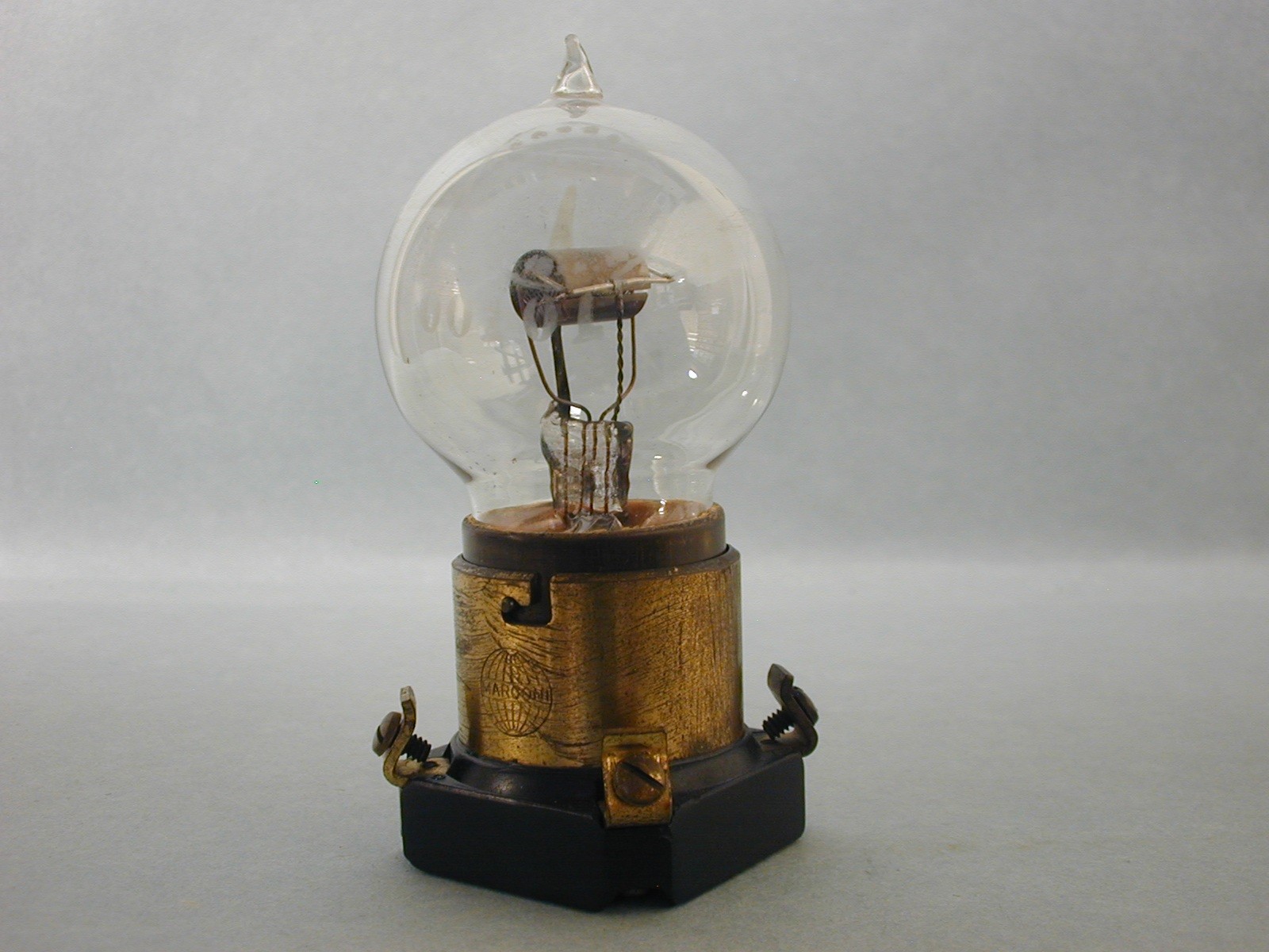
Much of the work by Ferrie and his team shared their work in Britain and the US. This is most obvious when the British bright emitter valve examples shown by this author are seen. Generally, the British R valve was ready for use in 1916 and were used by the British when radios were provided. Some of the first makers were Thomson-Houston (BTH) Edison-Swan, General Electric (GEC) (Osram) and Cossor. They had a spherical bulb and a 4 -pin base and it would be difficult to tell them apart from the French TM tube. Some R valves, however, had a different shaped bulb and were gettered. The R valve was the grandfather of all high-vacuum, low-power triodes, and transmitters in Britain, until 1925 when dull emitters replaced them. While this article deals with valves used during WW1, a mention of the Fleming diode must be made. His work continued the Edison-Effect light bulb and was frequently interrupted by patent litigation with DeForest and his triode but it did lay some of the groundwork for how these new valves should be made. G.W. White and Henry Round must be mentioned. White valves did their part in development but the Round valve and Round himself had a more profound effect on development. The BTH, (British Thompson-Houston), with extensive research done by GEC at the Osram works, produced the R-2 and R-4 valves used by the British Navy during WW1 in early1917. The R-2 and R-4 valves, again, were based on the French TM tube but with a semi-circular bulb and candelabra type base.
Please see the examples of British valves below.
Description of pictures 27-37 above:
Please click on each picture above for a larger view.
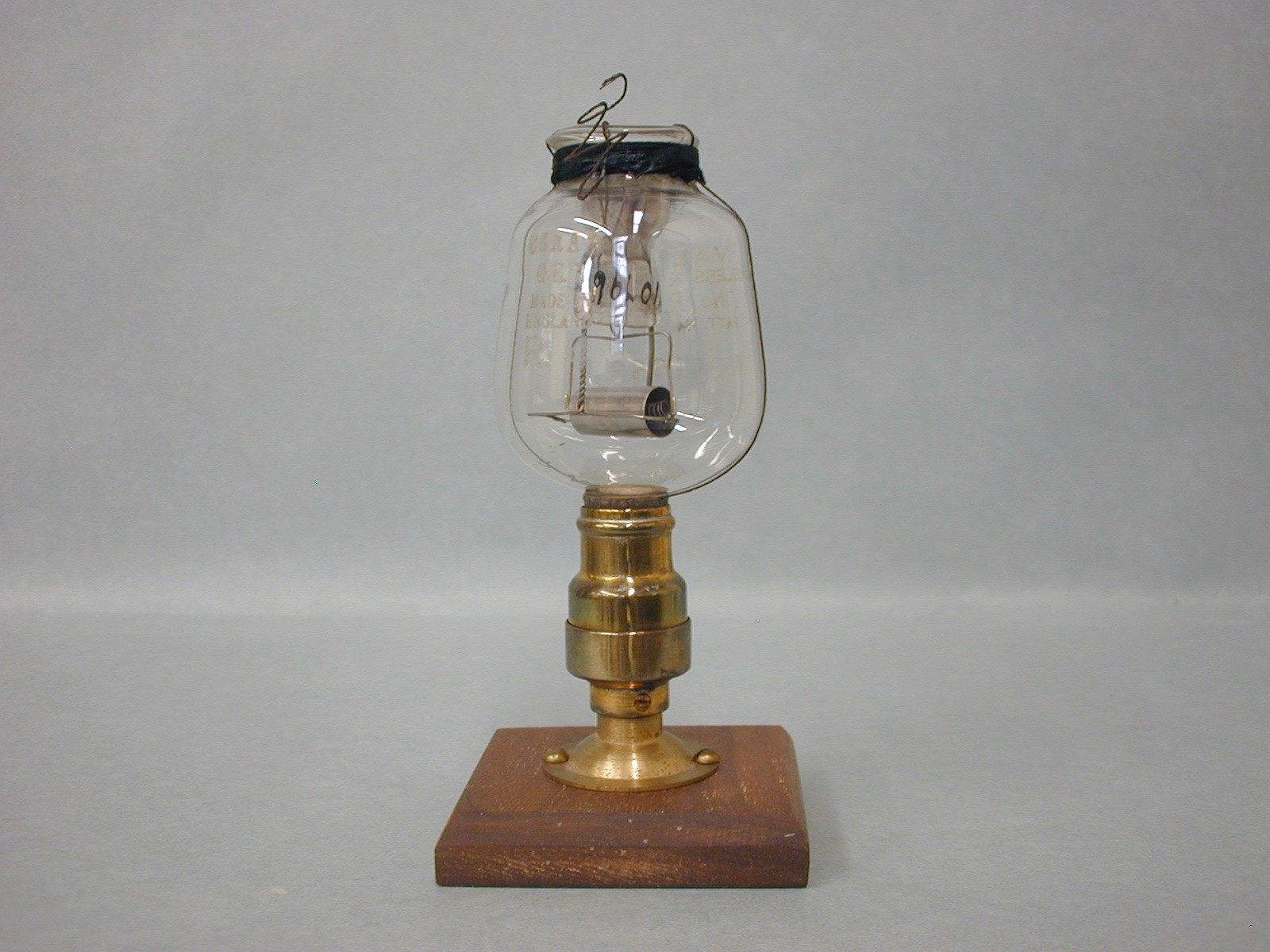
27. Fleming valve with Ediswan socket.
28. Fleming valve with Ediswan socket in a different shape.
29. Early original gallows type Fleming valve. Gallows frame is not period but home made.
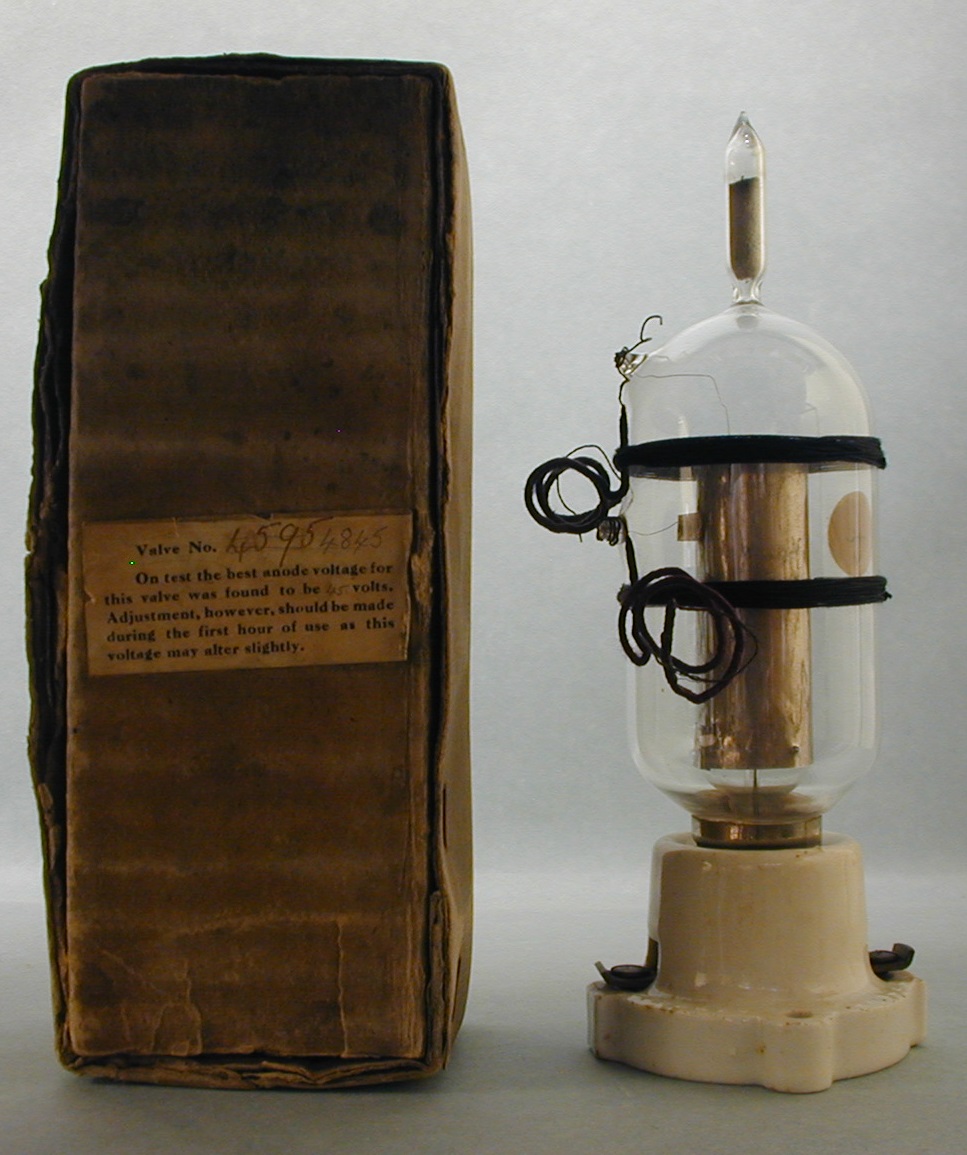
30. Round valve and shipping box. This type of Round valve was actually shipped to the front until other types of valves could be made.
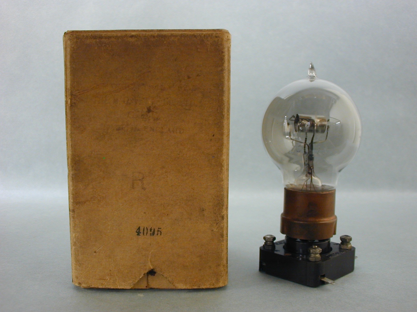
31. Very early R valve made by Osram-GEC and shipping box. This is the exact type of R valve that would have been supplied to the military.
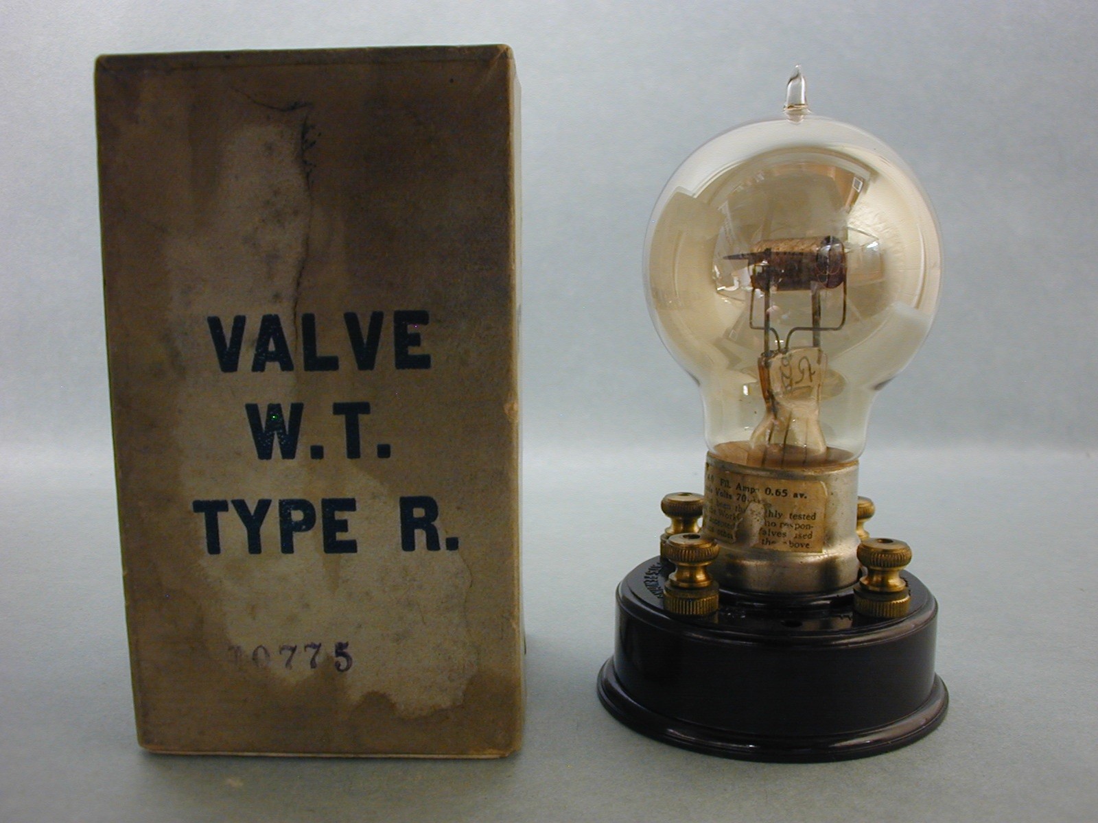
32. Another early Marconi R valve and shipping box made by MOV and or GEC with the BBC markings on the bulb. It has the early type of paper tag with the specs. Shipping box used is marked Osram, WT, type R. I cannot explain why the box is marked different but the serial numbers match on the valve and box.
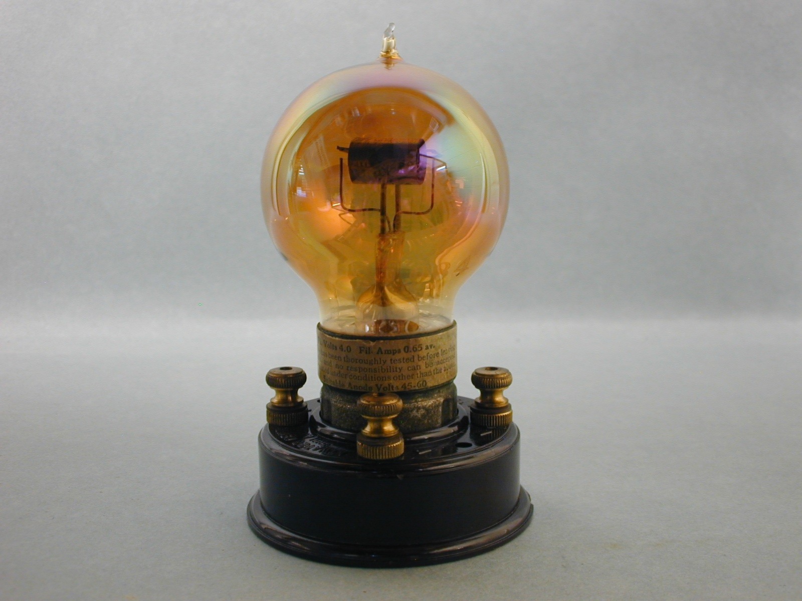
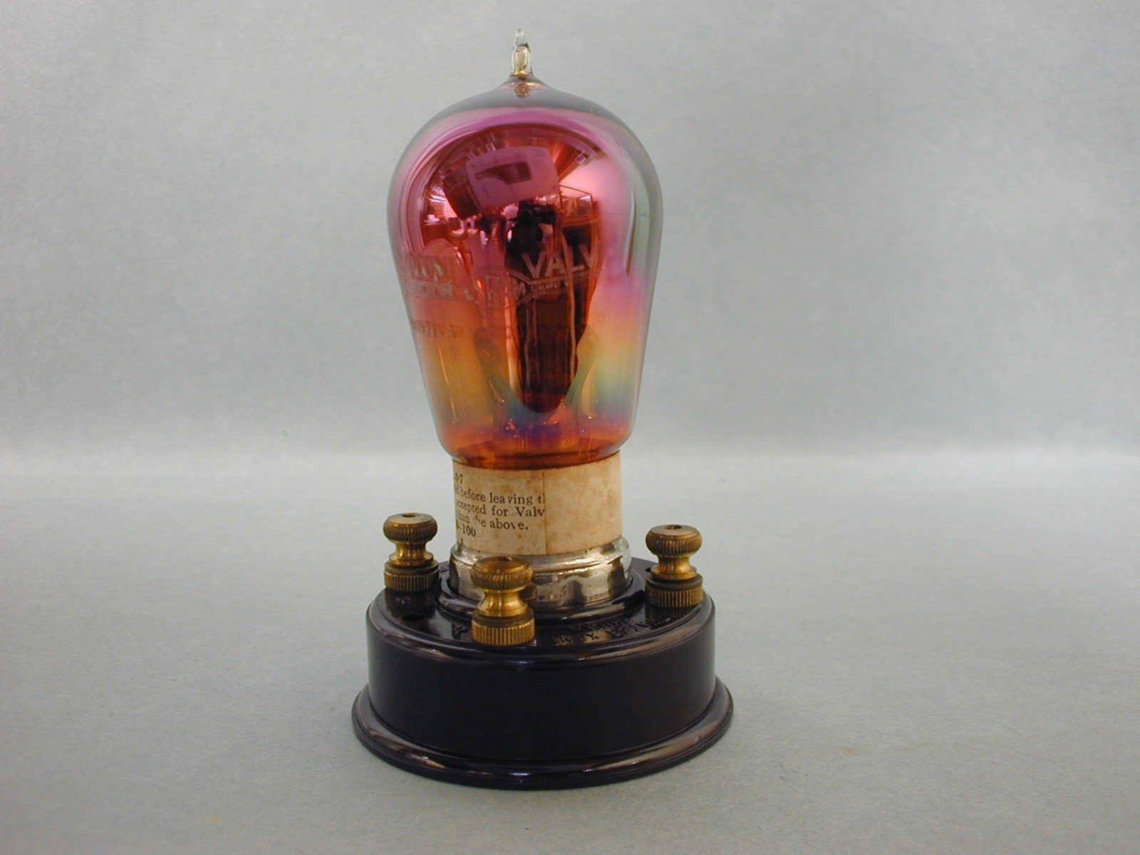
33.. Perhaps a post war Marconi Osram type R with a phosphorus getter giving it an orange color.
34. Another later post war Marconi Osram type R with the same phosphorus getter but in a different shaped bulb and a paper tag with the specs.
35. Osram- GEC made R4 valve. These types, including the R2, were used extensively by the British Navy.
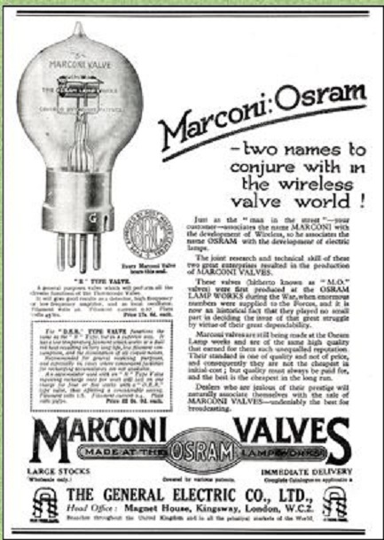
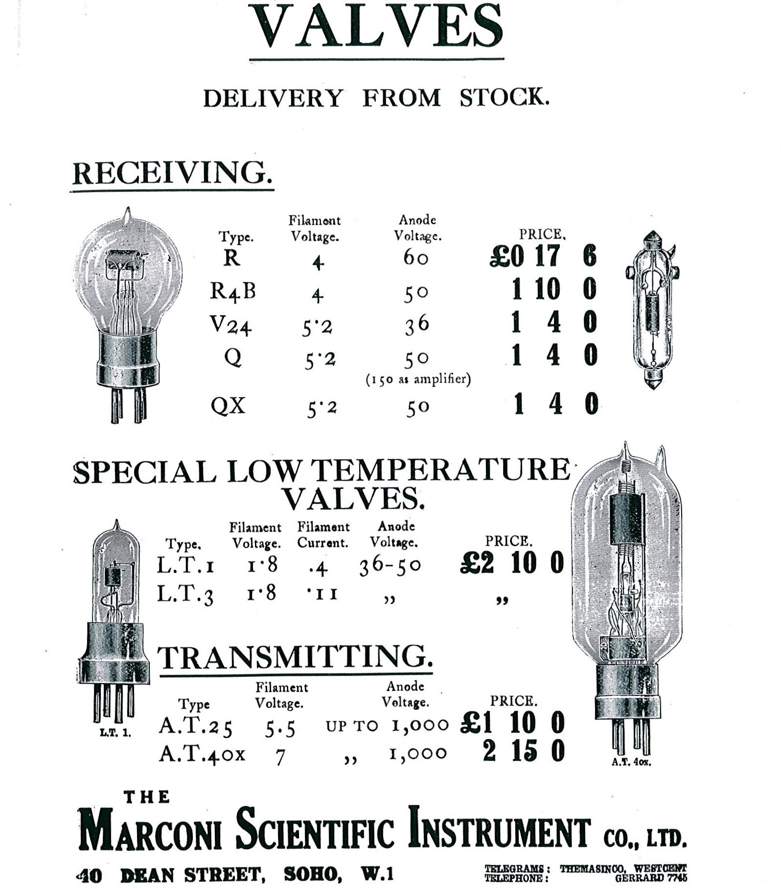
36 & 37. Ads for Marconi Valves from various sources.
United States
As we all know, Edison’s “Edison Effect” work on the light bulb laid the future groundwork for wireless communication. He did not give much thought about the possibilities of this new work starting with Fleming. Edison thought, at the time, his phonograph is what listeners wanted, to play their own taste in music, etc. Had he pursued the possibilities of what the Edison effect could become, he could have stopped Fleming in his inventive tracks had he looked at the big picture. so, Fleming, built his diode on the work of others just as he accused DeForest of doing.
While it is not within the scope of this article to comment on how DeForest came up with his idea on the triode, I will concentrate on the profound change that his invention made, the audion. DeForest did much work before the audion came along starting in 1904 at the World’s Fair in St. Louis. I will provide a link below in the sources section to these events as written by Frank Butler called “Making Wireless History With DeForest”, [6] his right hand man during this time frame up to around 1905. Beyond 1905, DeForest built many sending and receiving stations for the US Navy, including those used on US Navy war ships. So, while I will provide a few pictures of early DeForest tubes, there is much too much information that could be a 200- page article.
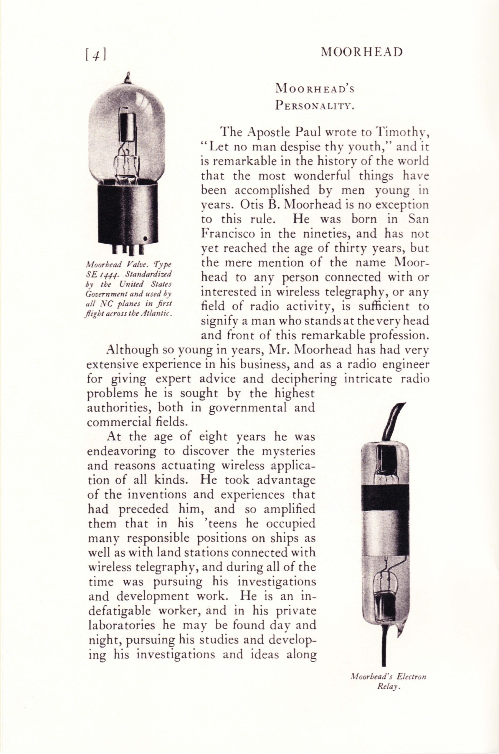
Western Electric, General Electric, Westinghouse Lamp Works made large contributions to the WW1 effort. Much has been written about these makers, including an article by this author about the war tubes made by G.E. I will show a link to.[7] I will try and do justice to the tubes made for the British Army by Otis Moorhead and the Moorhead Laboratories. It is believed that Otis Moorhead started experimenting with wireless at age 8. By 1914 he held wireless positions including as an assistant radio inspector for the American Marconi Company. In 1915 he worked for DeForest at the Panama-Pacific exposition selling audions. Moorhead then decided that he could make tubes and sell them as well. His old boss at Marconi, Major Allen Forbes, was convinced and gave him $200.00 and this along with another $500.00 from another investor started Moorhead’s venture. Moorhead along with Ralph Hyde, a former G. E. lamp factory superintendent, opened a small shop on Mission ST, San Francisco and in 1916 production began first tube Moorhead called the Electron Relay with ads in west coast magazines following. It did not take long for DeForest to sue Moorhead. A judge ruled that because DeForest and Marconi were locked in a patent battle, Moorhead could continue to make and sell his relay tubes but a bond was required to be posted until the patent litigation was settled. Because of the patent litigation between Marconi and DeForest over the grid introduction into the Fleming diode, no maker in the US could legally make or sell triodes, with few exceptions, with Moorhead being one of them. It is not known if Moorhead ever posted this necessary bond but probably not as DeForest sued him several more times. This prompted Moorhead to produce an external grid tube but this tube did not work. He continued to make and sell various forms of his relay and the situation went on for several years until the US entered WW1 when these patent restrictions were lifted as a matter of national security. This allowed Moorhead to make and sell his own line of tubes he sold to the British military to be used as a close replacement for their R valve and to the US military called the SE 1444. The British were glad to accept this help as their R valve was in great demand and the British makers could not meet this demand. I will show examples of these Moorhead made wartime tubes below. A 3-way deal between Moorhead, DeForest and Marconi lifted the ban on US made triodes following the end of WW1, however, the US government and the newly formed RCA company had other ideas that eventually put Moorhead, DeForest and Marconi out of business.
Description of pictures 38-51 above:
Please click on each picture above for a larger view.
33. Moorhead Laboratories external grid electron relay made to circumvent the DeForest grid patent. As it did not work, it is possible that Moorhead knew this and only released it to keep DeForest at bay, at least for a while.
34. Moorhead type R valve made as a direct replacement for the British type R. Hundreds, perhaps thousands were shipped to the UK as they could not keep up with the demand. It has the British standard 4 pin base for ease of replacement.
35. Moorhead made type B transmitter with the British standard base. Again, with this valve, thousands were shipped directly for use on the war front.
36. This Moorhead experimental type B transmitter was fitted with a Shaw standard 4 pin base for the convenience in testing. Quite rare in this form.
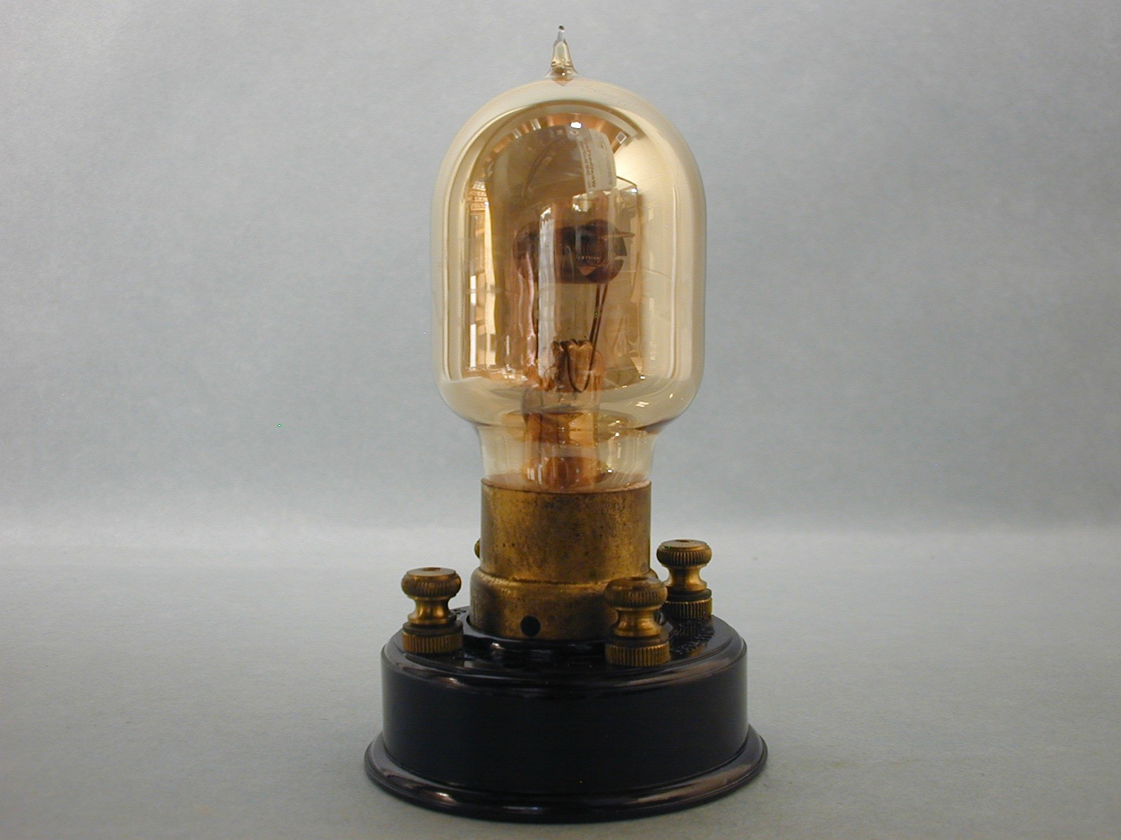
37. Another Moorhead valve called the VT-32. It has the golden tint from the phosphorus used as a getter. This type was introduced rather late in the war so many did not make it to the UK. Again, it has the British standard 4 pin base.
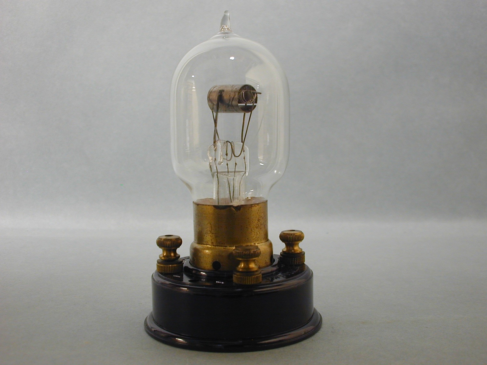
38. Same tube as # 37 but without the phosphor’s getter being used.
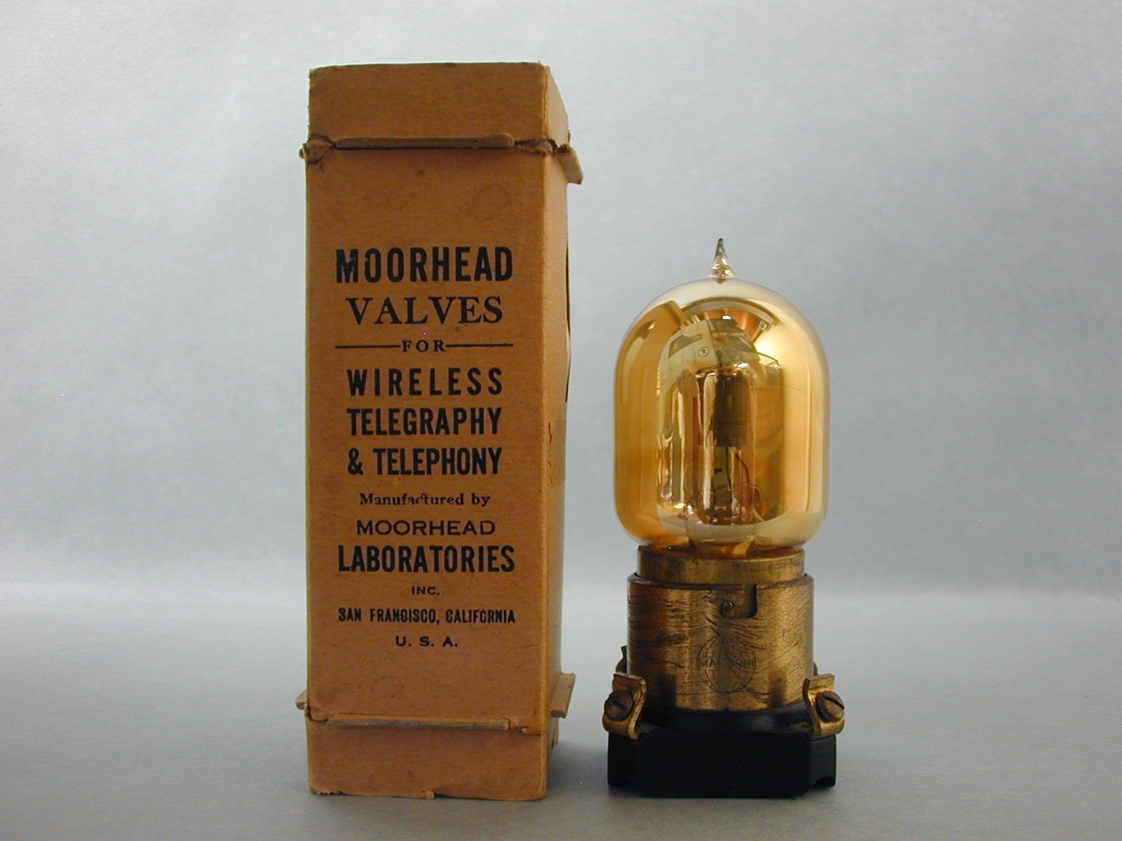
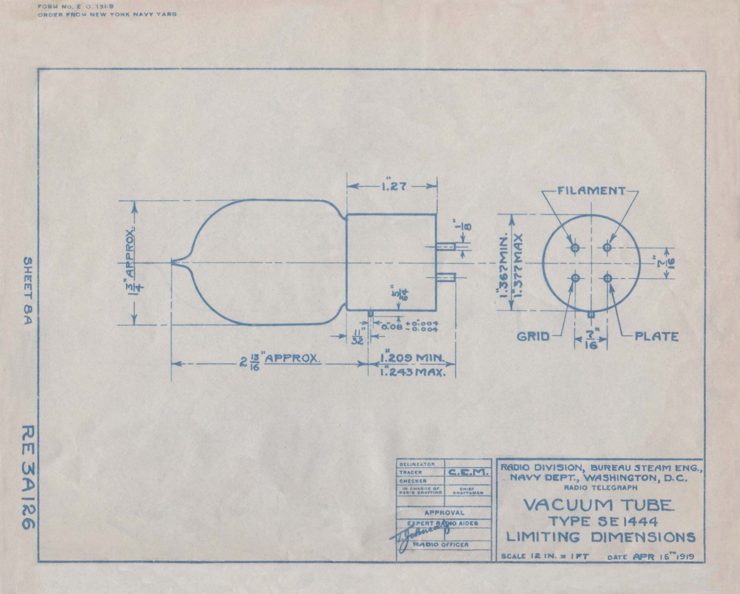
39. Moorhead made the SE 1444 for use in wartime by the US Navy and has the golden tint from the use of phorphorus. At the time, this was the only tube the Navy had that could be used as a detector and amplifier, a great testament to Moorhead Many were made and fitted on US warships. It was also the tube that was used on the first crossing of the Atlantic by the US Navy flying boat named the NC-4.
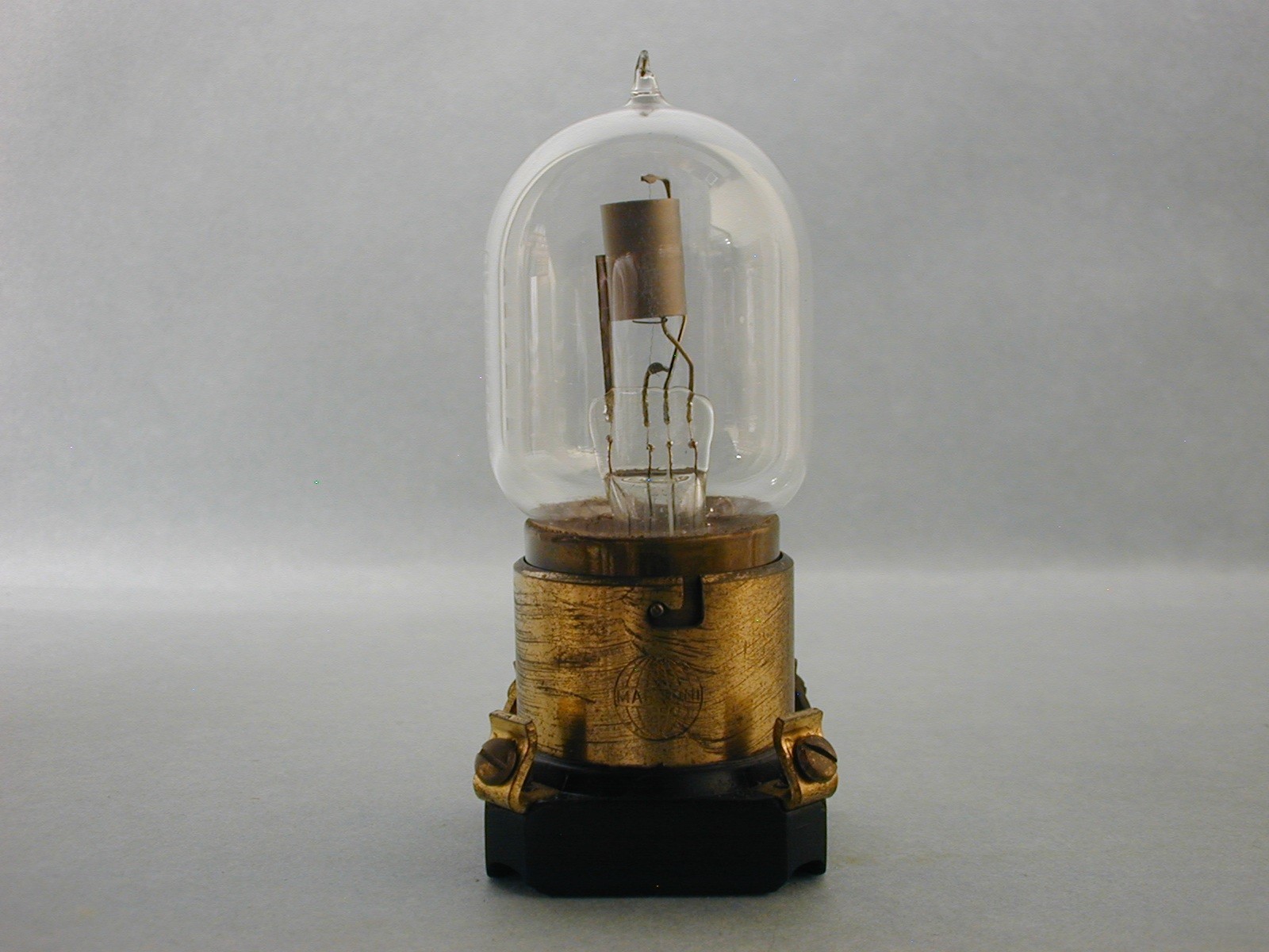
40. The same tube as # 39 but without the phosphorus gettering. Many of these tubes are shown with the post war Marconi VT sockets as can be seen.
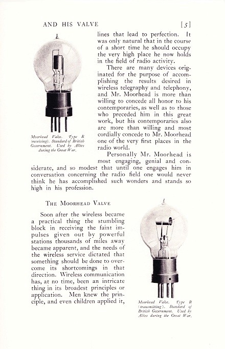
41. Page 4 is from the Moorhead catalog called “Moorhead and his Valve” and it shows the SE-1444 tube and the external grid electron relay.
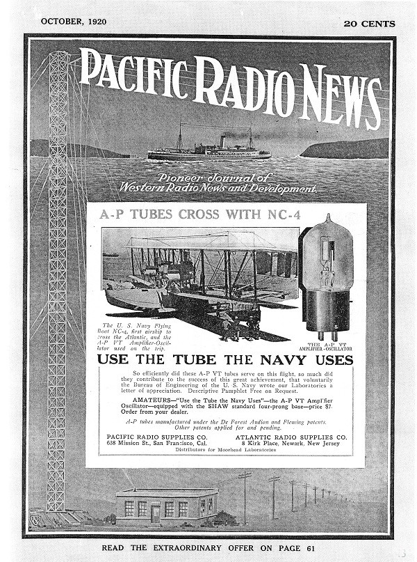
42. The Oct, 1920 edition of the Pacific Radio News had an ad showing the US Navy NC-4 after its arrival in Europe. It supports the fact that if the Moorhead tube is good enough for the US Navy, then it should be used by everyone. This fact is not far-fetched at all.
43. This blueprint was given to Moorhead as a guide in making the SE-1444 for the US Navy. The working specs would have been included as well on another document.
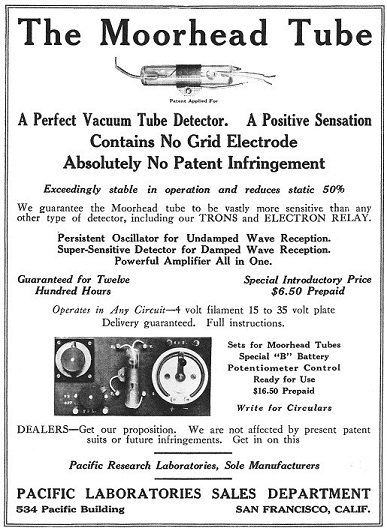
44. An ad for the external grid Electron relay that appeared in the Sept., 1916 edition of the Electrical Experimenter magazine. The claims in the ad are true in that it did not infringe any patents; however, it did not work as claimed.
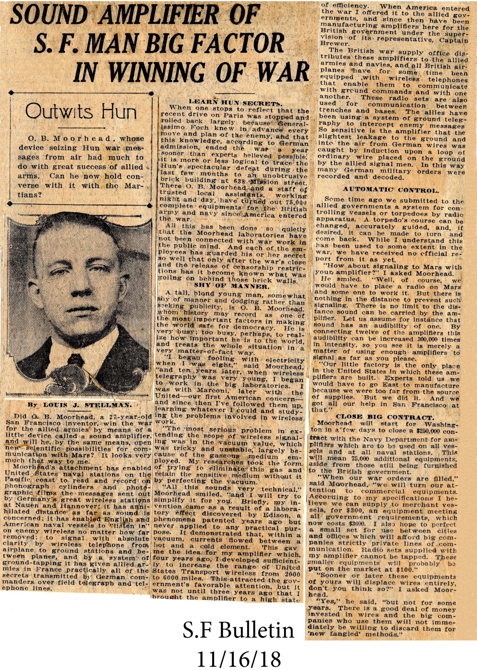
45. This article appeared in the Nov 16th, 1918 San Francisco Bulletin. Many of the claims are true but readers will be able to clearly see that some ideas were just not going to come true.
46. Another page from “Moorhead and His Valve” catalog, this time talking about the type R valve and the type B transmitter. Again, many claims are true but their use in WW1 speak for themselves as being very successful.
Sources: Click on the hyperlinks below in blue font to see the articles
- “About the French TM-Valve- The Forerunner of the British R- Valve,” Fons Vanden Berghen. I asked for & received permission to use his 1-7 pictures. Follow this hyperlink- A_FTM or it is on vacuumtubearchive.com under same name under articles.
- “British Radio Valves-The vintage Years: 1904-1925”, Keith Thrower
- “Saga of the Vacuum tube,” Gerald Tyne, 1977.
- “Grande Et Petit Historie DE Lampe TM” Robert Champeix, the original article can be found here: G_P or it is on vacuumtubearchive.com under the same name under articles.
- “The Moorhead Story,” Bill Condon, TCA magazine, Vol. 5, #2, April, 2003 on vacuumtubearchive.com
- “Making Wireless History with DeForest”, Frank Butler, Radio Broadcast starting in Vol. 6, #4, Dec. 1924. B_D or its on vacuumtubearchive.com under the same name under articles.
- “From Research Lab To The Field – G.E.’s Vacuum Tube Contributions During World War 1 1915 – 1918”, Joe Gruber, TCA magazine, Vol. 17, #6, 2015. 11_2
- Figure #43 is from the paper collection of Jerry Vanicek.
- Figure #45 is from History San Jose via Will Jensby.
- Chapter 2, “The Great War and the First Triode Designs”, Abraham, Bloch, Blondel, Van Der Pohl, from the book “History of Nonlinear Oscillations Theory in France (1880-1940). Find it here: T_G
- “Electrical Experimenter”, Dec., 1915, “By Wireless Phone from Arlington to Paris”, P_1, P_2
- Marconi Catalog, 1912-13, in authors collection here: MC_1
Leave a Reply