

The first trans-Atlantic flight by the US Navy is an often-overlooked event in aviation history along with the most important part of the communication equipment necessary to complete that task- the vacuum tube. By orders from the Assistant Secretary of the US Navy, Franklin D. Roosevelt, plans for large, long-range flying boats were drawn as early as September, 1917 to combat the German U-boat menace during WW1. Once the war ended, Roosevelt wisely expanded these plans to include the first trans-Atlantic crossing. The Navy choose The Curtiss Aeroplane and Motor Company, Garden City, Long Island, New York, to supply the plane design and engines. Holden Richardson, a graduate of the Naval Academy, was also chosen to help with those designs. The Liberty 12-cylinder engine designs were the result of shared patents and were manufactured by many motor car companies such as Buick, Packard, etc. for the war effort. Of course, they had to be altered for use on planes and this was accomplished by Curtiss and Richardson. The name NC (Navy- Curtiss) was chosen. After several years of planning and overcoming difficulties, the NC-1 thru NC- 4 planes were built, tested and ready. By May 8th, 1919, the 4 NC planes started out for their destination, Lisbon, Portugal. [1] [2]
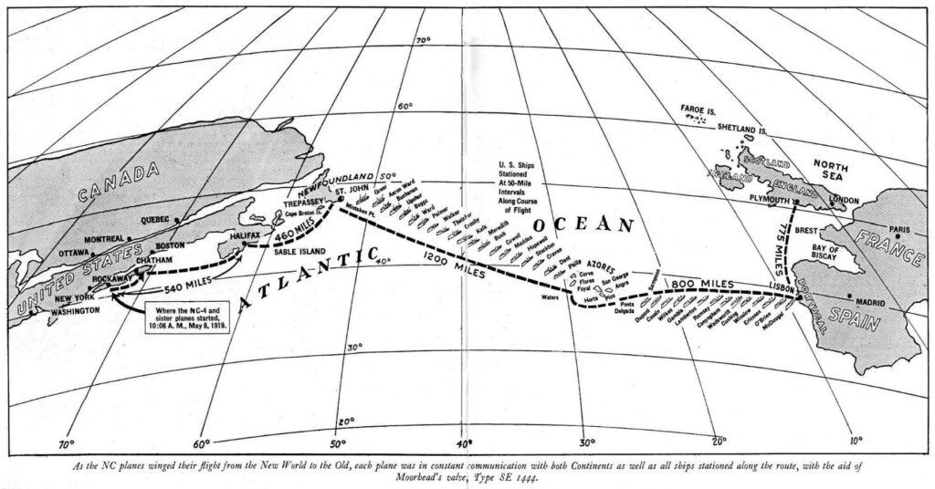
Fig. 1 shows the chosen route. [3] 68 US warships were stationed every 50 – 75 miles along the chosen route so the NC planes could keep in constant radio contact and determine if they were veering of course too far. Although each person of the six- man crew had an important job, once in the air the radio man’s ability to do his job correctly could be called a matter of life and death. The navigator may argue that point. The NC-4 was the only plane to complete the over 4500- mile trip and almost 54 hours of actual flying time on May 30th, 1919. The trip to Plymouth, England was for sentimental reasons alone and is included in the total miles. [2] All four planes were provided a radio direction finding compass but no parachutes.
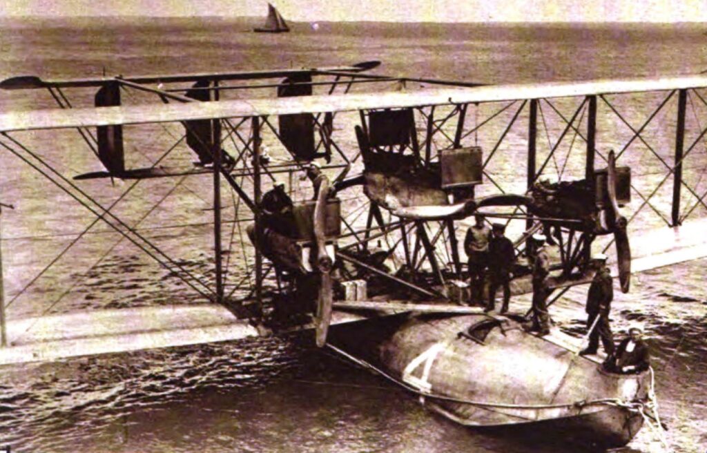
The four 350 HP “Liberty” engines can clearly be seen in this picture of the NC-4 shortly after its arrival in Plymouth, England, shown in fig. 2. [2] The three front engines were used for lift and the rear engine was used for push. Not so easily seen below the center front and rear engines is the GE wind generator used for the planes radio equipment power.
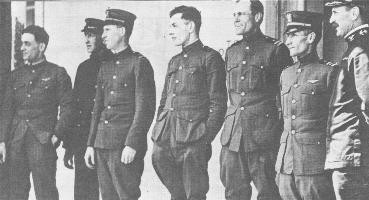
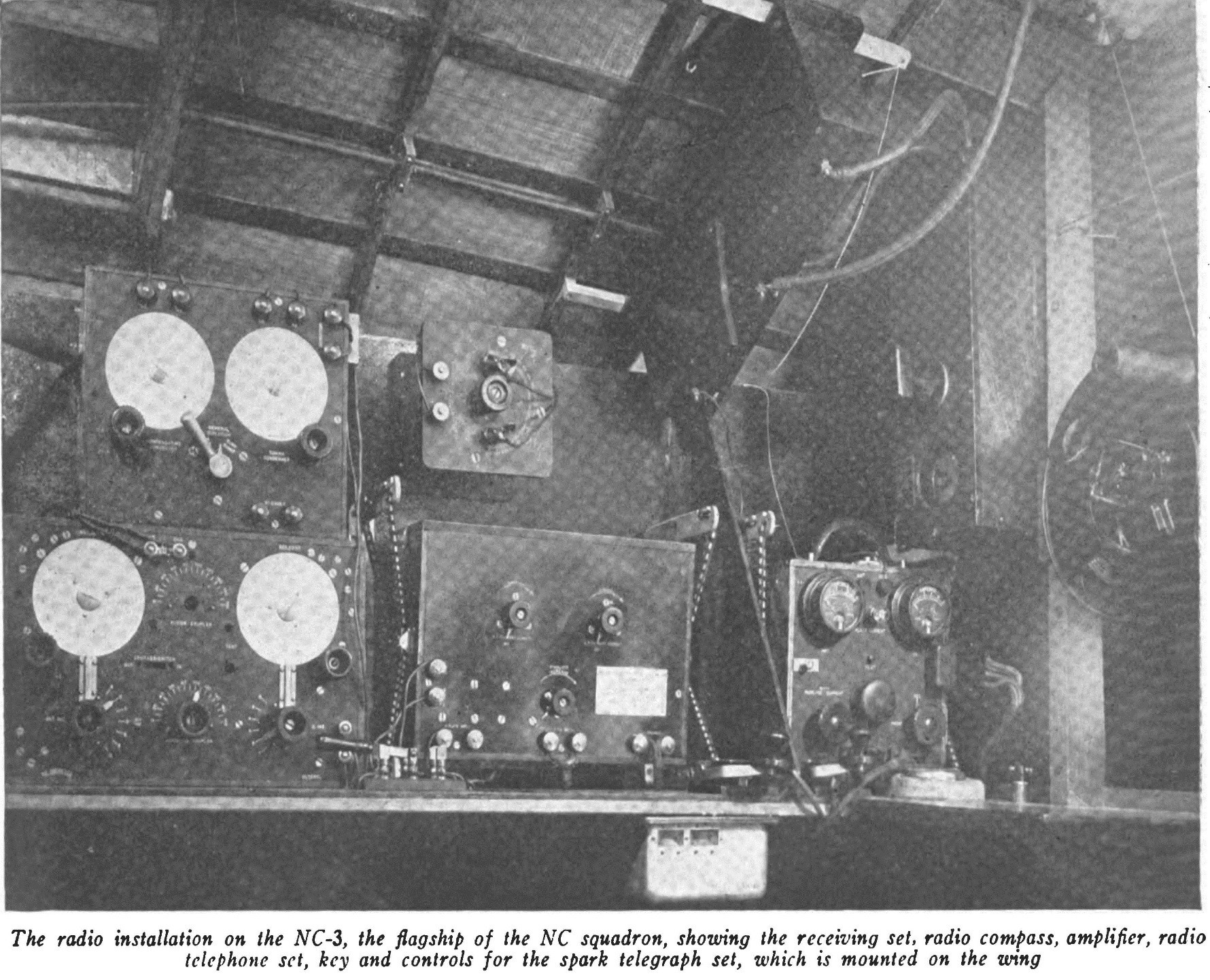
Fig. 3. Crew of the NC-4- Left to Right
Stone: Pilot, Rhodes: Machinist Engineer, Hinton: Pilot, Rodd: Radio Operator, Breese: Engineer, Read: Commander and Navigator, Jackson: Navy base ship Melville.
Fig. 4. shows the radio equipment aboard the NC-3. [4] The NC- 4 equipment was identical. A very good source to identify the radio equipment along with a complete 3 part narrative of the entire flight was written by the radio operator on the NC-4, Ensign Herbert C. Rodd, US Navy. [5]
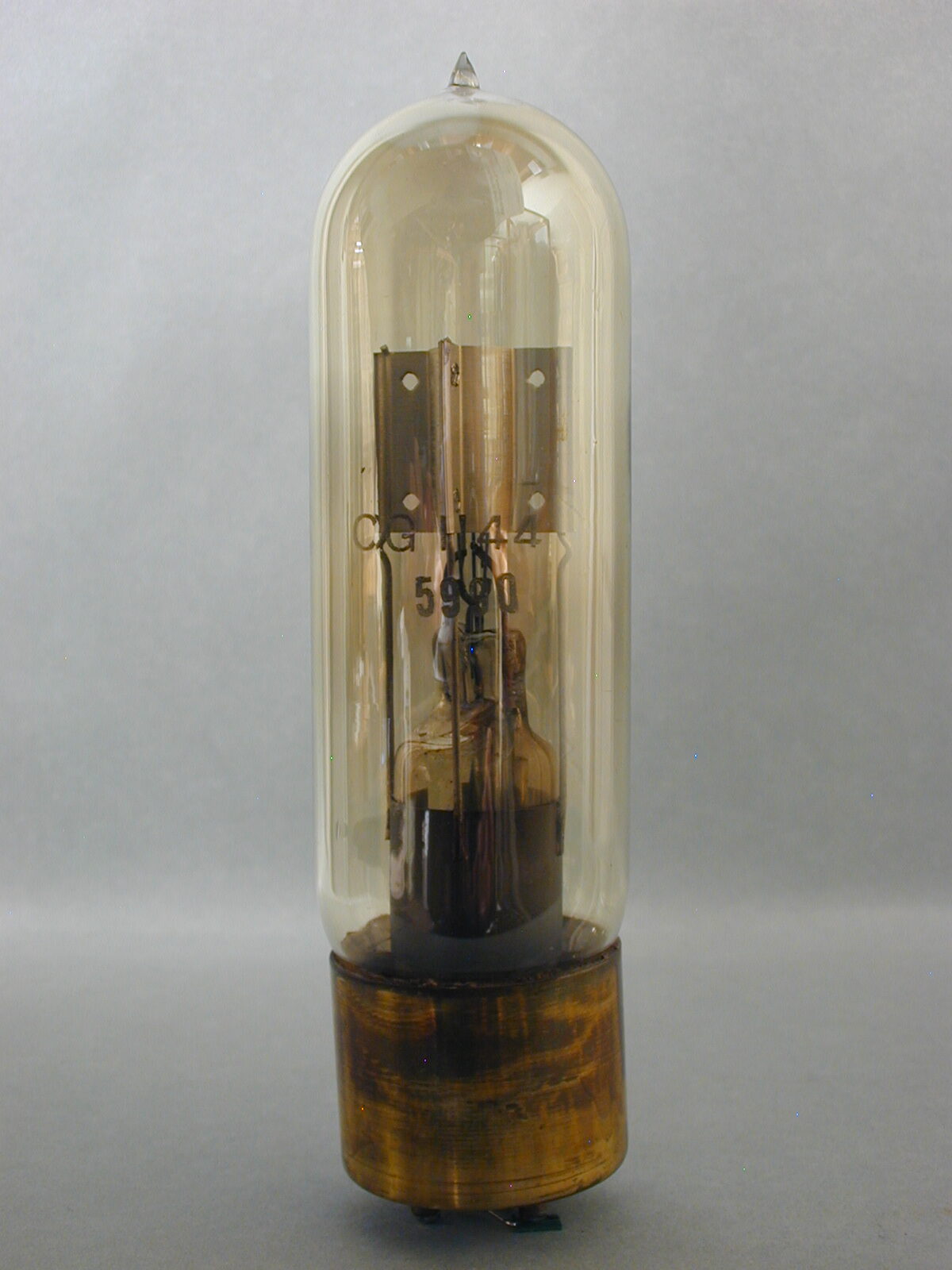
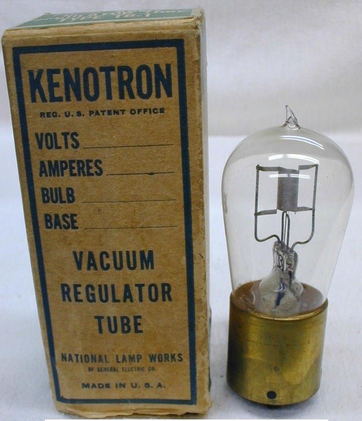
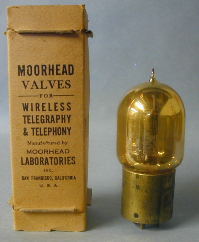
Fig. 5 shows the GE CG 1144, also known as the VT-18 or type U Pliotron. Fig. 6 is the GE TB-1 and in Fig. 7 is the Moorhead SE 1444. Over the course of the flight many messages were received and transmitted but the greatest distance of a received message by the NC-4 was 1325 miles between the NC-4 and the US Navy Ship USS George Washington, a great achievement by the SE 1444. [5]
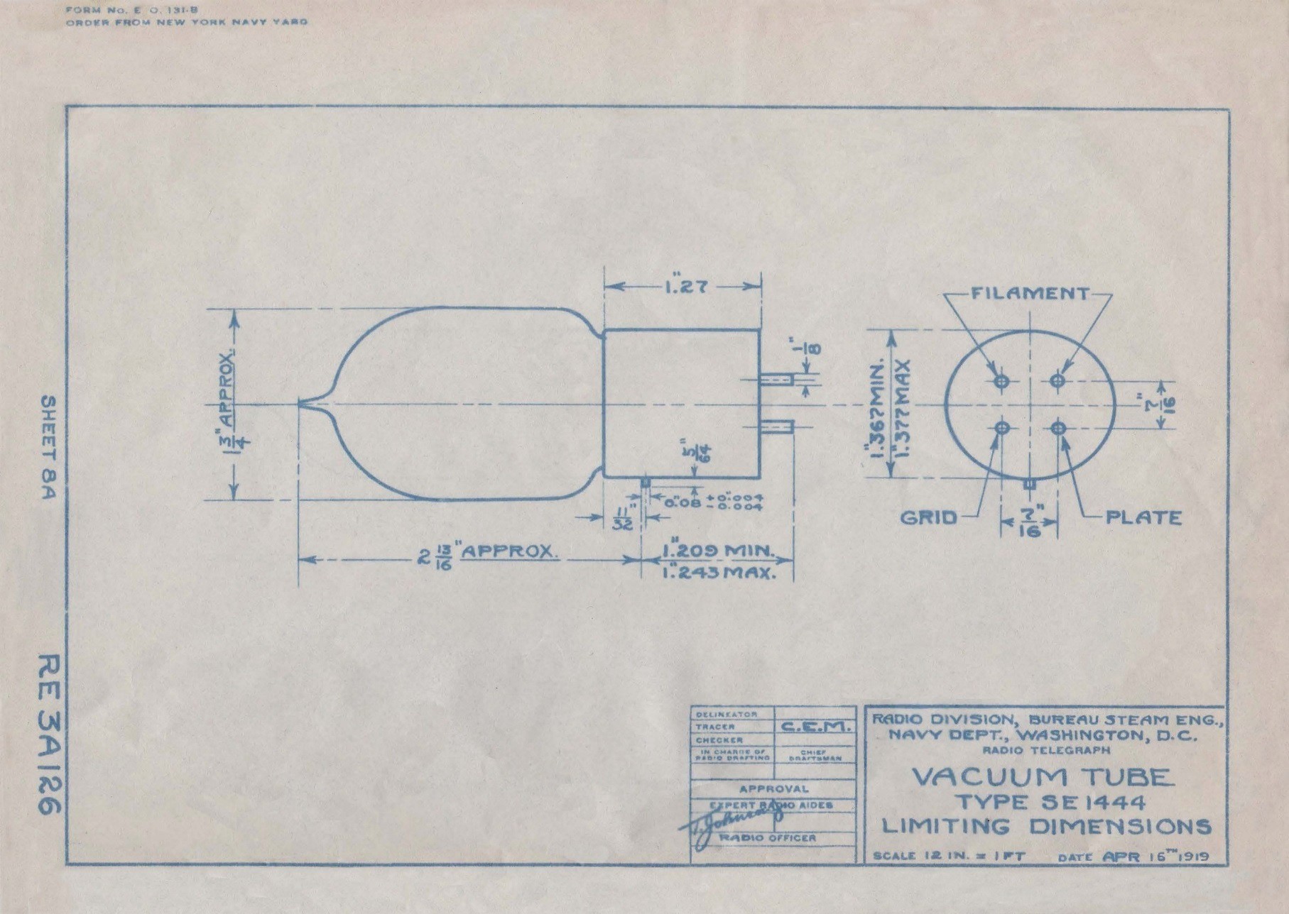
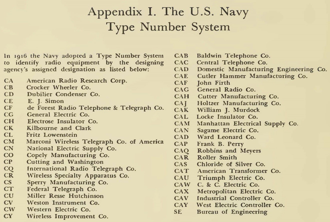
Shown in Fig. 8 is the US Navy limiting dimensions outline drawing for the SE 1444 dated April, 1919. Earlier versions of this drawing must have been provided to Moorhead to manufacture the SE 1444 as they were made for the US military during WW1. George Clark devised the numbering system for the US Navy. SE 1444, for instance, would be a tube designed by the Navy: SE = Bureau of Steam Engineering, and 1444 would be a consecutive number assigned according to the number of sets and components made up to that point. The CG 1144 tube would be a commercially designed tube: CG = C for commercial, G for General Electric and assigned the number 1144. [6] The TB-1 was a US Army (Signal Corps) tube and their numbering system is unknown to this author at this time.
The George Clark US Navy numbering system is shown in Fig. 9. [7]
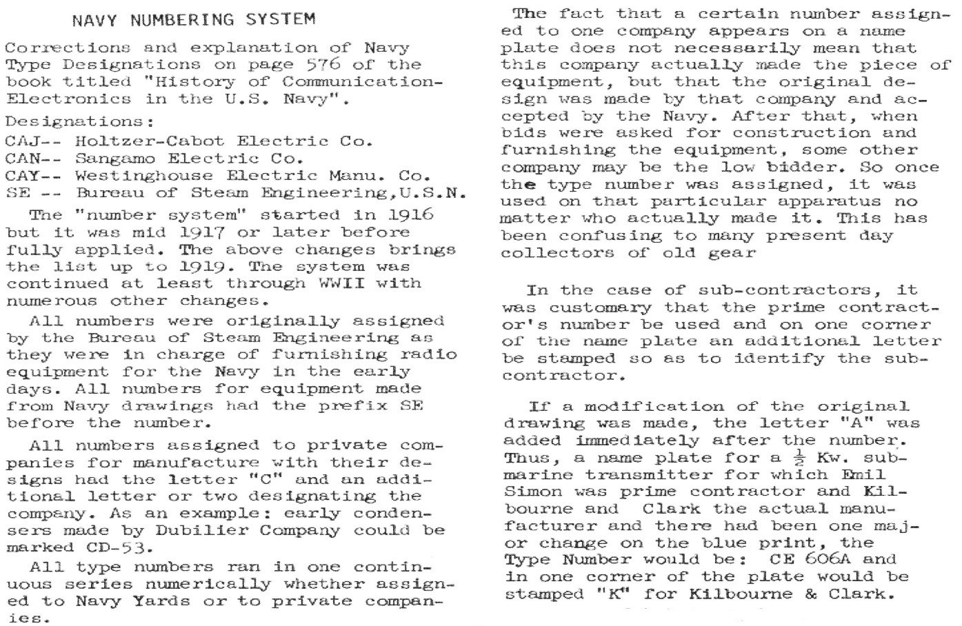
Bob Palmer wrote several corrections and an explanation to George Clark’s numbering system some years later, shown in Fig. 10. This is an unknown source file in the authors’ collection.
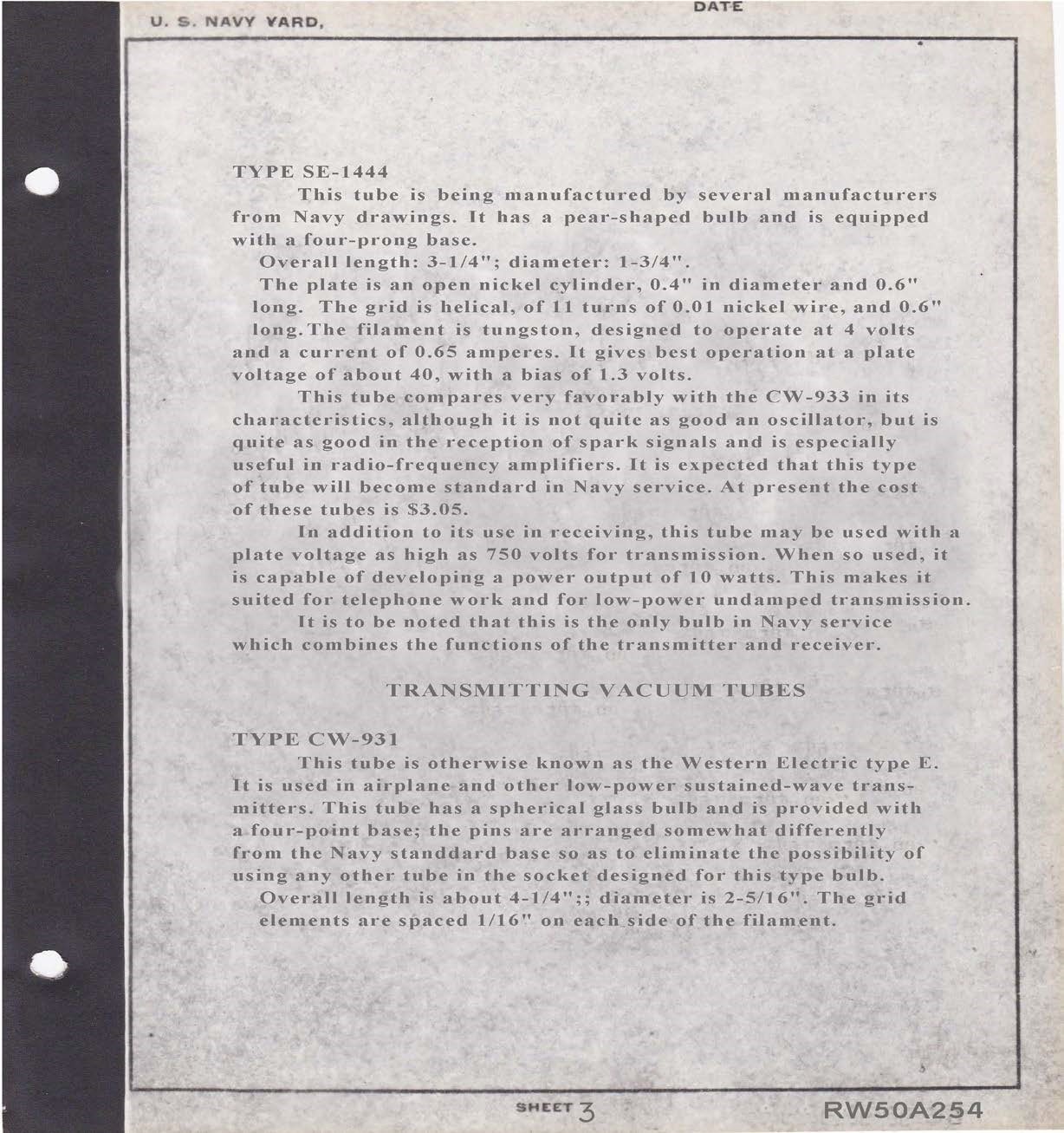
The Navy Bureau of Steam Engineering was responsible for suppling tubes for US Naval use. Some of these types were assembled into an example collection after the war. Lieutenant W.A. Eaton, US Navy, was given the task of assembling and describing the now famous Eaton Navy tube collection. Shown in Fig. 11 is a scan of sheet three of the appendix of that report, dated February, 1919. [8] The SE 1444 is described in great detail and said to be the only vacuum tube in use by the US Navy that could be used as transmitter and a receiver.[9][10] The first sentence in the document also states several tube manufacturers were making their version of the SE 1444 from the US Navy drawings. From that sentence one could assume that some unmarked Moorhead SE 1444 lookalikes seen in collections today may have been legitimate contributions by other manufacturers.
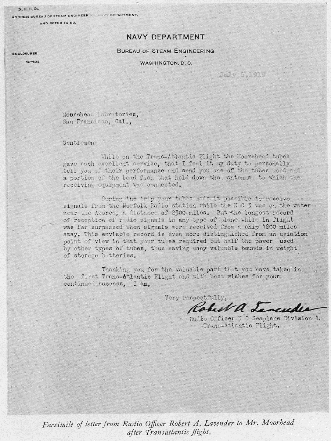
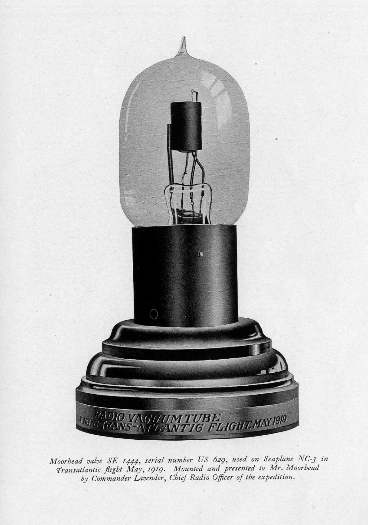
The US Navy was quite impressed with the performance of the SE 1444 and subsequently wrote a letter to Moorhead thanking him for the valuable part he played in the first trans-Atlantic flight. They included with the letter one of the SE 1444’s used on the NC 3 during the flight and an antenna part. Fig. 12 is a scan of that letter as it appeared in a company brochure. [3] The letter was signed by Lieutenant Commander Robert A. Lavender, US Navy, the radio operator on the flagship NC 3 and the radio officer in charge of the entire NC fleet.
Shown in Fig. 13 is a scan of the US Navy presentation tube as it appeared in a Moorhead company brochure. [3]
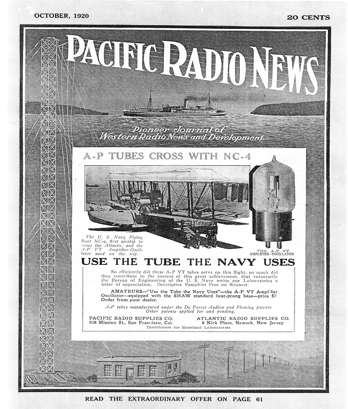
Otis Moorhead was working for the company he had started and Henry Shaw was president at the time the A-P advertisement shown in Fig. 14 appeared in the October, 1920 Pacific Radio News. The tube shown in the ad was called the Atlantic-Pacific VT but in fact was the renamed SE 1444. [11]
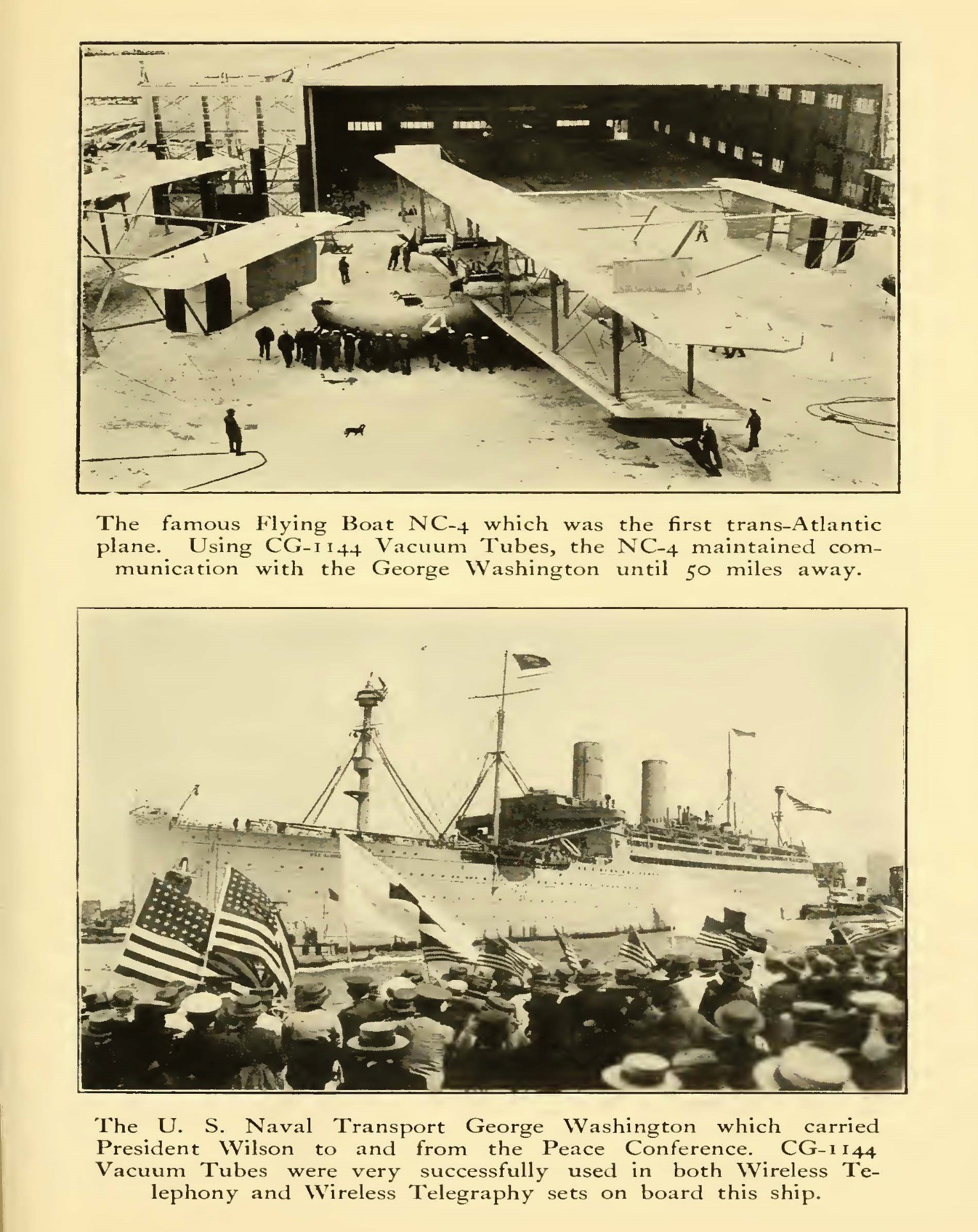
The communication distances of 50 miles using CG 1144 tubes referred to in the top picture in Fig. 15 [12] were preliminary tests made in 1918 after the completed assembly of the NC 4. Much greater distances were achieved in the 1919 expedition. Oddly, the SS George Washington (original name), lower picture, was a German (1908) built ocean liner seized by the US Government when we entered WW1. It was also one of the first ships to send wireless reports to the Titanic regarding a particularly large iceberg seen off the Grand Banks of Newfoundland on April, 14th, 1912. That reported area is exactly where the Titanic struck an iceberg and sank.
Footnotes:
All material used in this article are in the Joe Gruber collection.
Double click the hyperlink in Blue below to read the first hand article by Ensign Rodd, radioman on the NC-4.
- References:
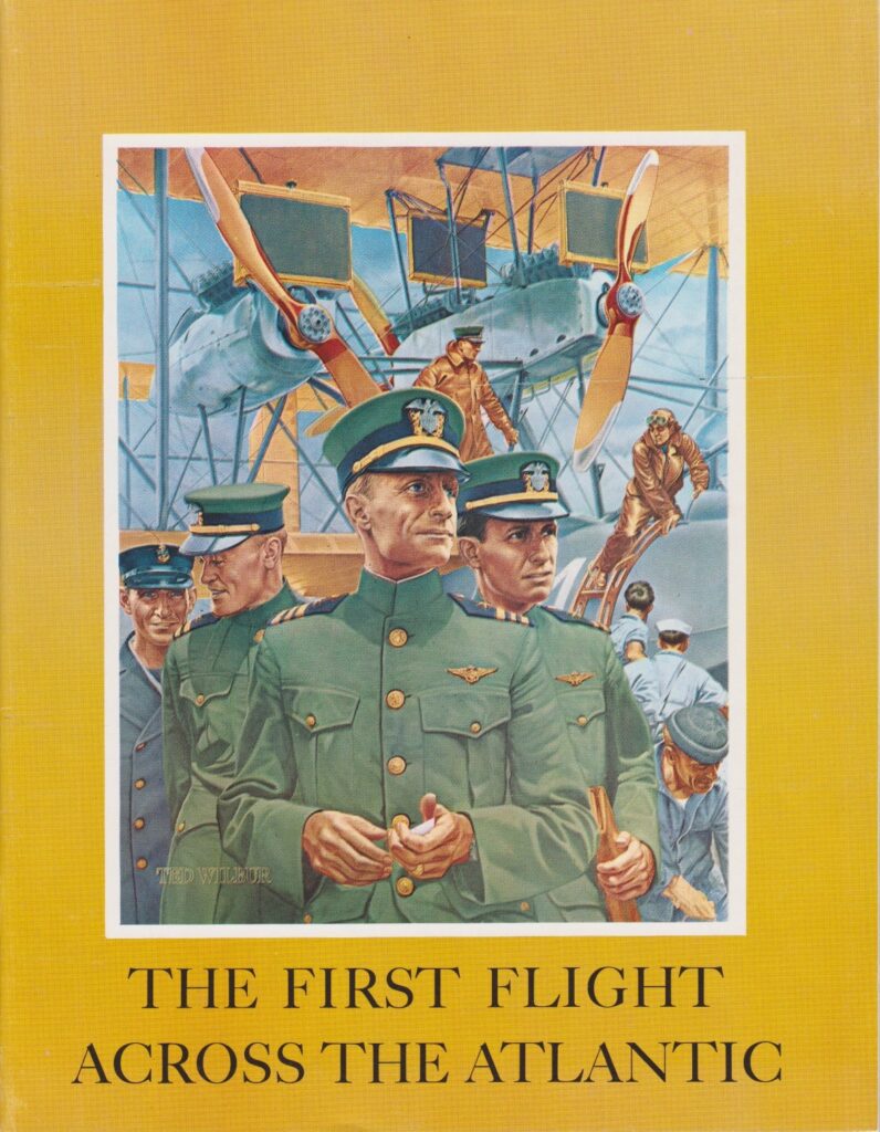
- 1. Smithsonian Institution, National Air and Space Museum, Washington, DC. “The First Flight Across the Atlantic”, 1969.
- 2. Russell, James and Moore, William, “The United States Navy in the World War”, 1921, pages 207-222
- 3. Moorhead, Otis, “Moorhead and His Valve”, 1919.
- 4. Flying Association, Inc., “Flying Magazine”, monthly magazine, June, 1919.
- 5. Wireless Press Inc., “The Wireless Age”, “Across the Ocean on the NC- 4” by radioman Ensign Herbert C. Rodd, 3 articles appearing in the Aug., Sept., Nov., 1919 issues. Complete article here: R_A
- 6. Howeth, Capt. L. S. US Navy, “History of Communications- Electronics in the United States Navy”, 1968, pages 218, 219.
- 7. same as 6, page 576
- 8. scan of document in the authors collection.
- 9. Eaton, W.A., US Navy, Radio Test Shop, US Navy Yard, Washington, DC., appendix to: “Description of Vacuum Tubes in Navy Service”, February 3rd, 1919, in a report coded RW50A254.
- 10. Clark, George H., “Radioana Collection”, Archives Center, National Museum of American History, Smithsonian Institution, Washington, DC.
- 11. scan of magazine cover in authors collection.
- 12. General Electric Company, book, “The National in the World War, April 6th, 1917- November 11th, 1918”, between pages 244 and 245.
Leave a Reply