
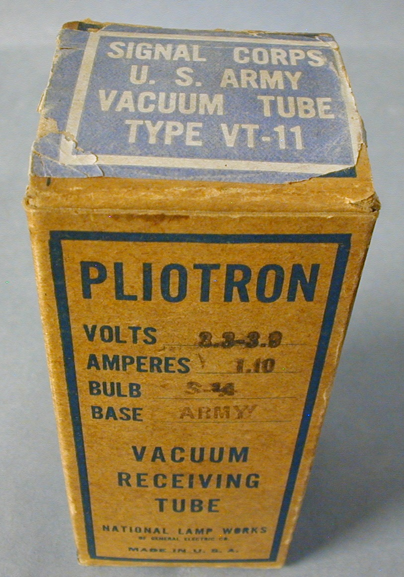
General Electric’s Vacuum Tube Contributions – 1915 – 1918
by Jerry Vanicek and Joe Gruber
Expanded and revised article that appeared in the Vol. 17 #6, December, 2015 TCA Magazine.
Beginning in 1912, the Research Laboratory at GE was constantly experimenting and making developmental samples that could be used in their general quantity production fully expecting to supply future demands. [1]. It must have become apparent very quickly what needed to be done at the General Electric Company when, in late 1917, the US Navy placed the first order for 1000 receiving tubes. This order was based on 6 examples. William C. White quote- “Early in December, the Navy had come forward with a request for tubes, an order being placed for 1000 receiving tubes on the basis of six examples produced by the lamp factories sent by the Research Laboratory to the Navy”. This was the first actual order for tubes from the Government to be placed with General Electric and the necessary steps were immediately taken to build up an organization in the lamp factories, laying out equipment for considerable quantity production”. [2]
All pictures below can be enlarged by left clicking on them.
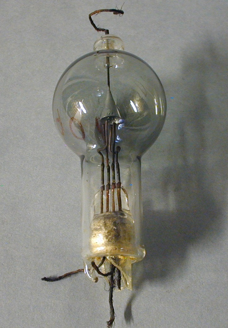
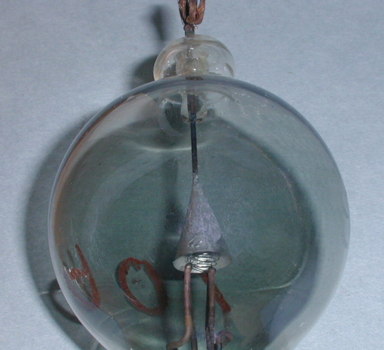
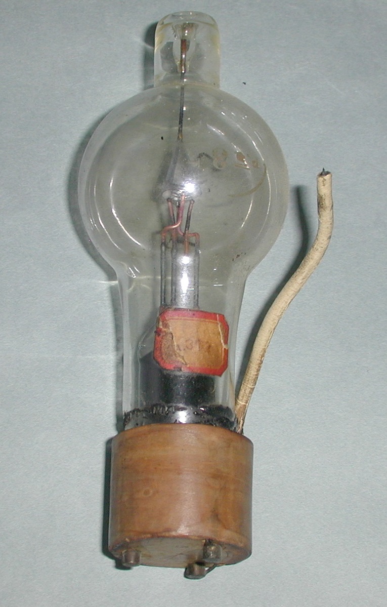
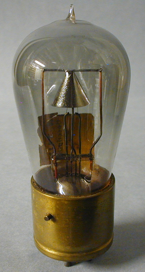
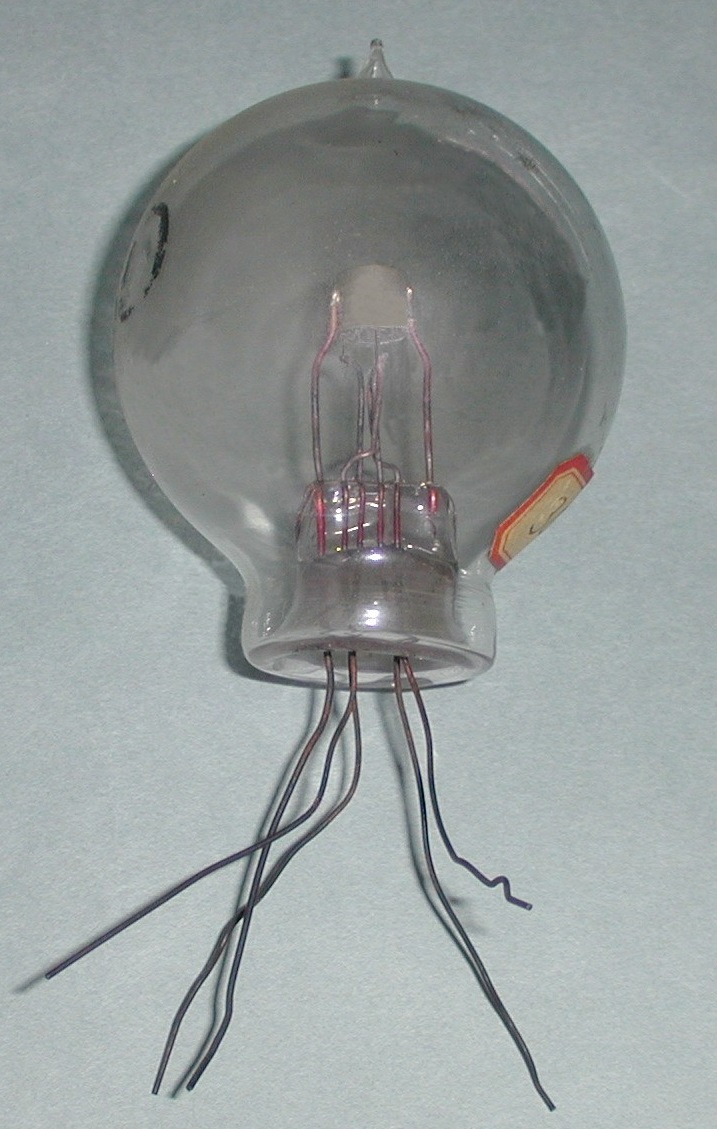
Fig. 1. The tube shown in Fig. 1 is a developmental pliotron triode receiving tube designed by W. C. White in 1915 or 1916. [3]. It has a conical plate, indicative of their early work, supported by a rod through the top of the tube connected to a multi-strand wire. 4 wires extend through the bottom- 2 for each leg of the filament and 2 for each leg of the grid all using multi-strand wire. This tube also has the number 706 written with a red material on the bulb that is considered to be a GE museum accession identification and the letters p a. and number 408 etched on the bulb. [4]. Since this pliotron came from the GE museum in Schenectady, it can be said with some confidence that it was made at the GE Research Lab in Schenectady by White. [4]. It could have possibly been sent to Nela Park for their research at a later time and returned.
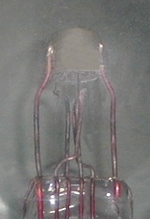
Fig. 2. Also shown is a close-up of the anode. Another example observed in the Vanicek collection, shown in fig. 2, has a white composition material DeForest type base.
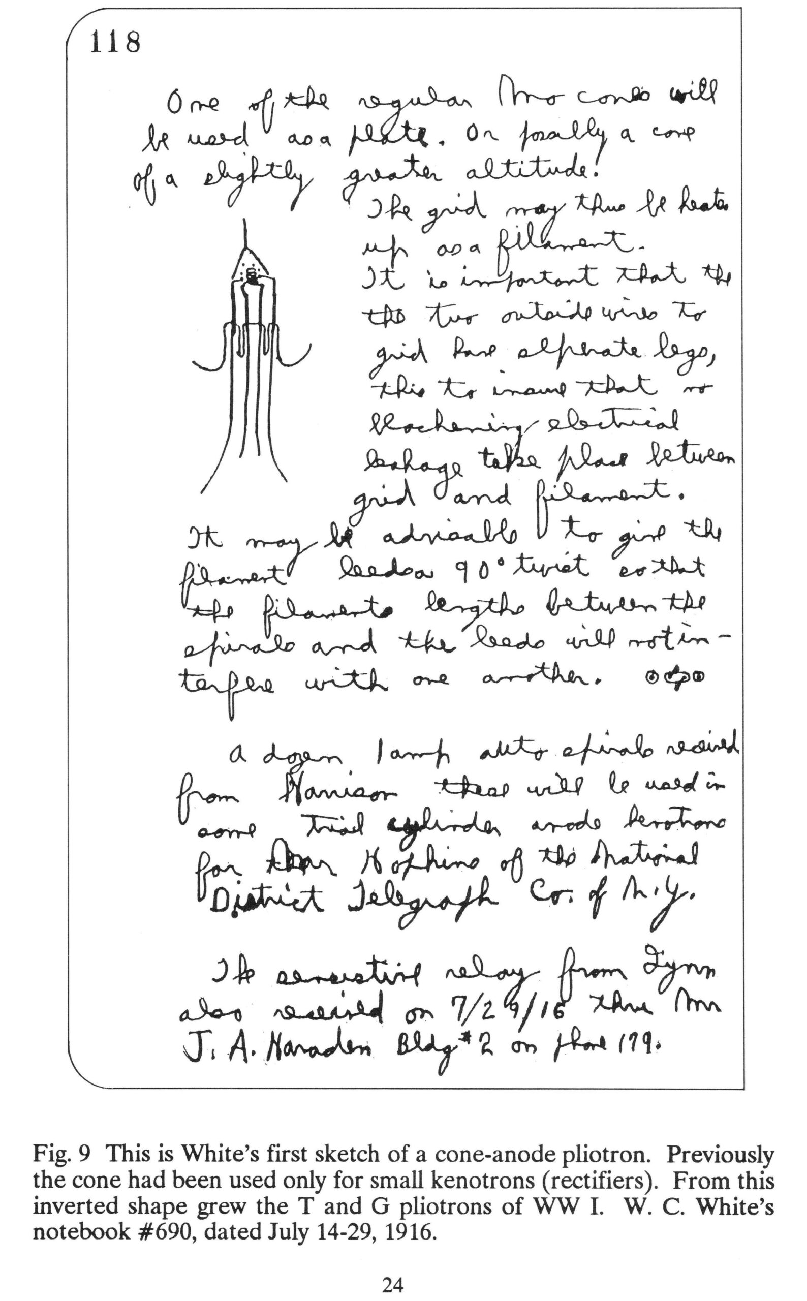
Shown in Fig. 3 is a page from J. M. Anderson’s notebook #690, dated July 14-29, 1916. [5]. The information from this page in the notebook gives a great deal of evidence that the cone shaped plate pliotron in Fig.1 was a developmental step towards the G.E. research lab tubes they named the type G and T pliotron’s. [5]. In one sentence in White’s notebook, he advises giving the filament leads a 90-degree twist so as not to interfere with one another. [5]. The example in Fig. 1 has a 90-degree twist in the grid leads.
The experimental tube in Fig. 4 is thought to have been made in 1917 from the earlier White design and presumed to have become the type T pliotron transmitting tube. [6]. The anode is cone shaped and resembles the internal structure of the prototype in Fig. 1. No markings on the press make it difficult to know where it was made but probably at the Research Lab at Schenectady. This tube was purchased by this author from the Tyne collection and is the same exact tube shown in the Saga on page 153.
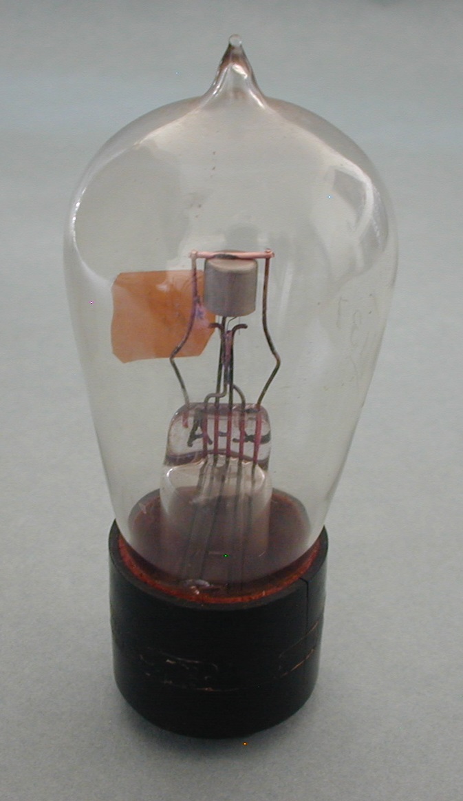
The small receiving pliotron, shown in Fig. 5, may possibly be the type of one of the first six examples made by the GE Lamp Works and submitted to the US Navy by the GE Research Laboratory [7]. It was probably made in early or mid 1917. The anode is cup shaped but the remainder of the general internal structure design will be shown to have been carried through to the final design of the 1000 tubes shipped to the Navy, namely, the CG-886’s.
Fig. 6. Close-up of anode in fig. 5 is shown in fig. 6.
Another more refined and familiar looking developmental tube leading to the CG-886 is shown in Fig. 7. [8]. Notice the similarity to the internal structure to the example shown in Fig. 5. The cup shaped anode is now part of the design of this tube and must have been quite successful. It has what became the de Forest US Navy standard 3 pin base made of a composition material, in this case black in color. This tube was probably made around mid or late 1916 or 17 and was a step closer to the final design. G137 is etched on the glass of this tube so it was probably made at the Nela Park Research Lab in Cleveland, Ohio.
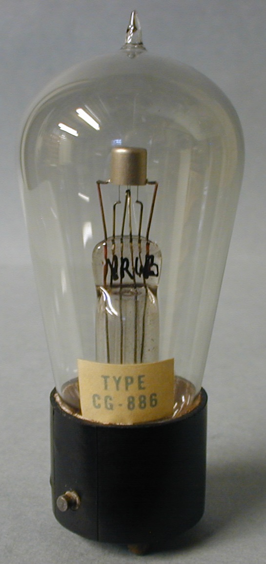
Fig. 8. In early May, 1918, the 1000 GE type G pliotron’s ordered were supplied to the US Navy they called CG-886. They were to be used as a detector, amplifier and oscillator on land stations and on ships by both the US Navy and Signal Corps. [9]. The CG-886 had a 3 pin base with the side pin being the 2nd connection to the filament. The base is made of a composition material, again, like those supplied by de Forest to the Navy. These 2 design features were to be abandoned quite soon in favor of the more familiar 4 pins on the bottom of the base. This tube was made at Nela Park.
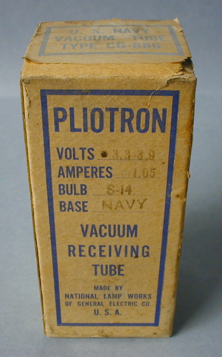
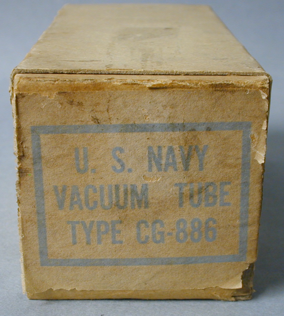
Figs. 9 & 10. This is the shipping box along with the labeled box top.
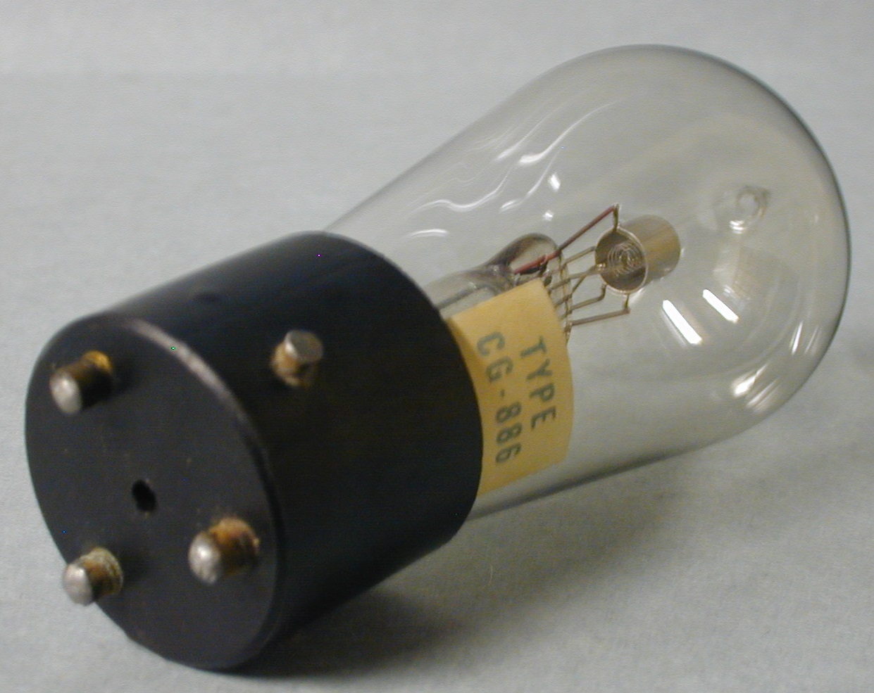
In fig. 11 the three- point base of the US Navy CG 886 can be seen.
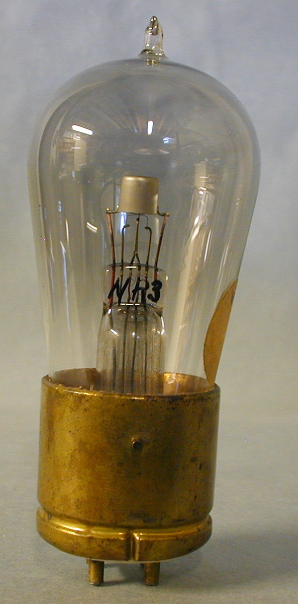
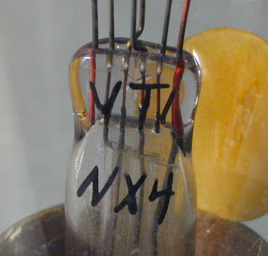
Fig 12 shows an advanced experimental version of what would become the US Army VT-1 and the US Navy CG 890. The internal structure has been simplified from the example in Fig.7 and slightly different from the tube in Fig. 8 with its electrical characteristics improved as well. Also, a 4 bottom pin configuration has been added, unlike the 3 bottom pins as in the CG 886. NR3 is written on the press that indicates it pre-dates the VT-1, NX4 in Fig. 13. A paper tag has W9 written on it that must be an internal developmental codethe National Lamp Works of G.E. used.
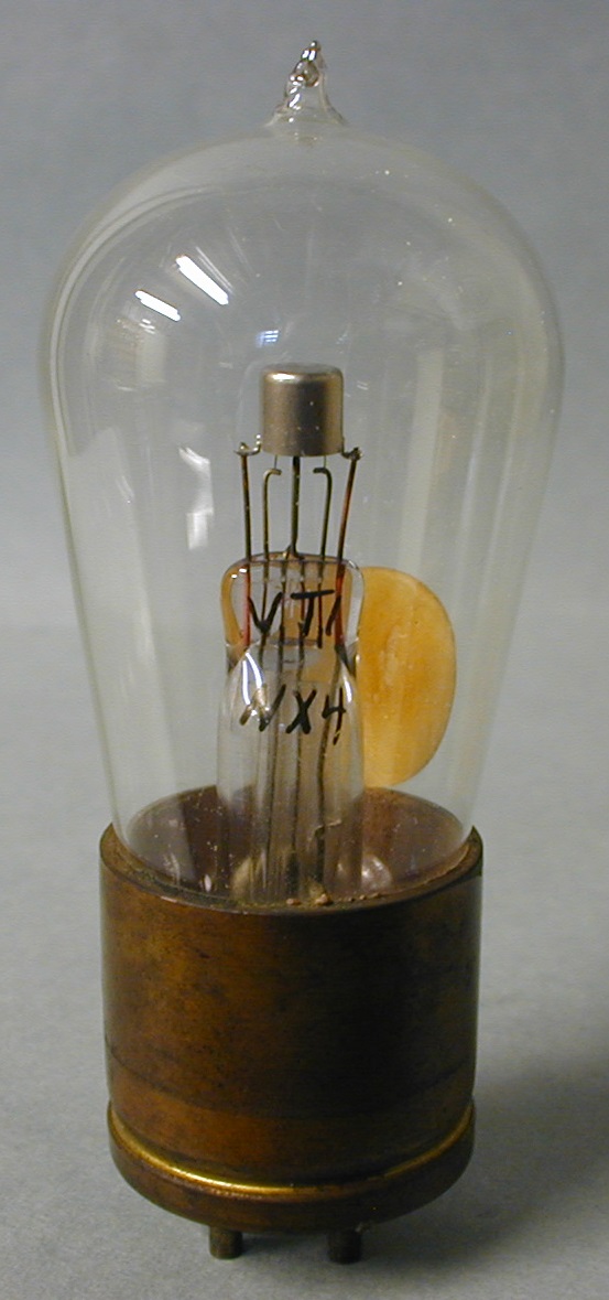
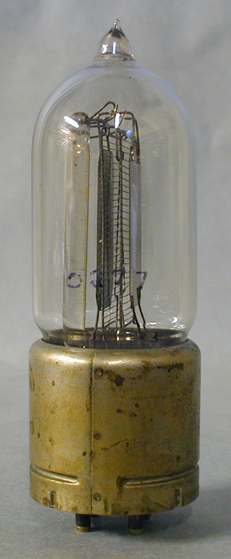
See Fig 13 and 14 for the VT-1, NX4. At this point the US Signal Corps become interested in the CG-886 tube but requested that the filament be redesigned to meet the Signal Corps voltage needs, etc. [10]. Samples were submitted and accepted for manufacture and the final design is shown in fig. 12. GE marked the tubes VT-1 NX4. Tubes marked NX4 are confirmed to be the very first purchased by the Signal Corps [10] and were made at Nela Park. [10]. The number of tubes marked in this manner is speculated to be quite low. Few collectors realize that like Western Electric’s VT-1, General Electric also named a tube VT-1. This will be proven in the documents to follow.
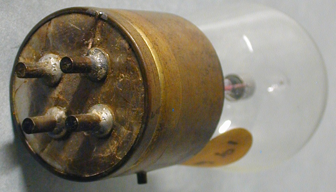
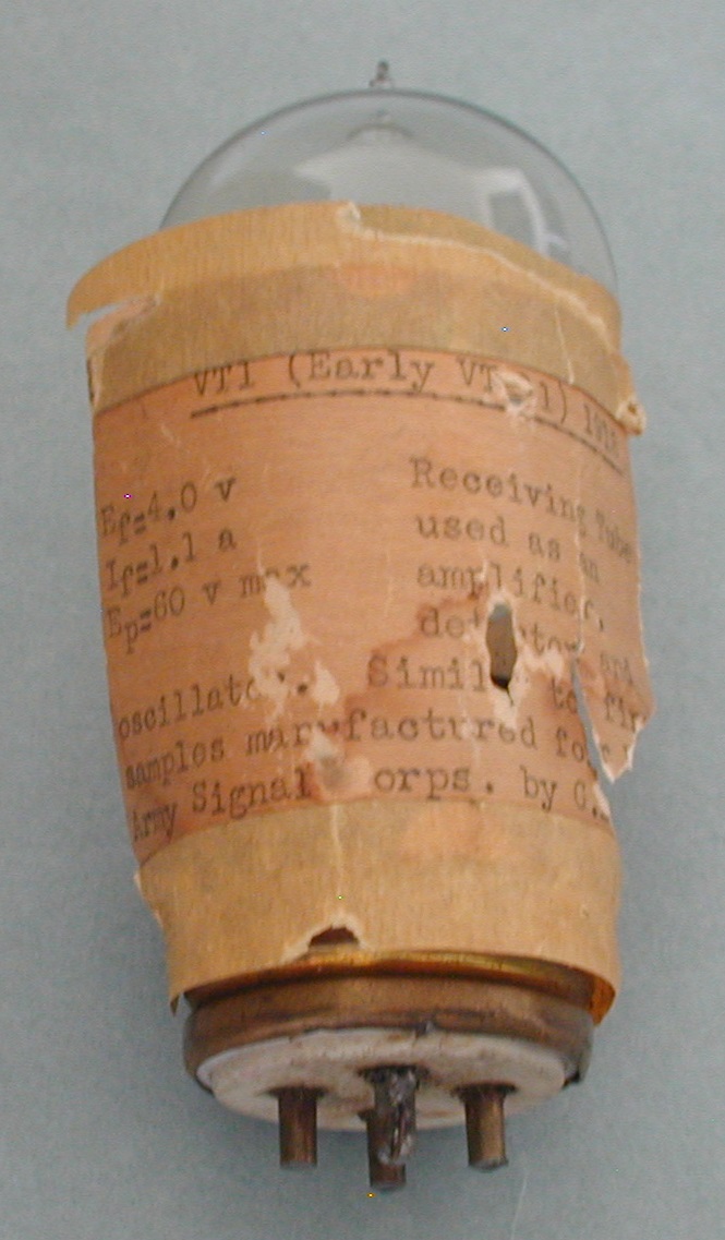
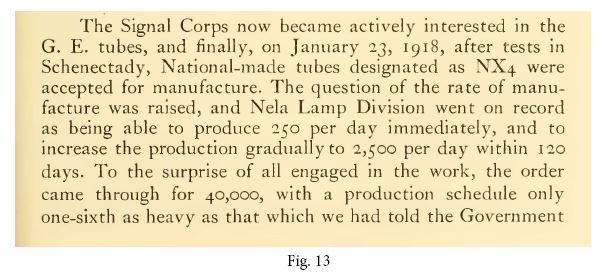
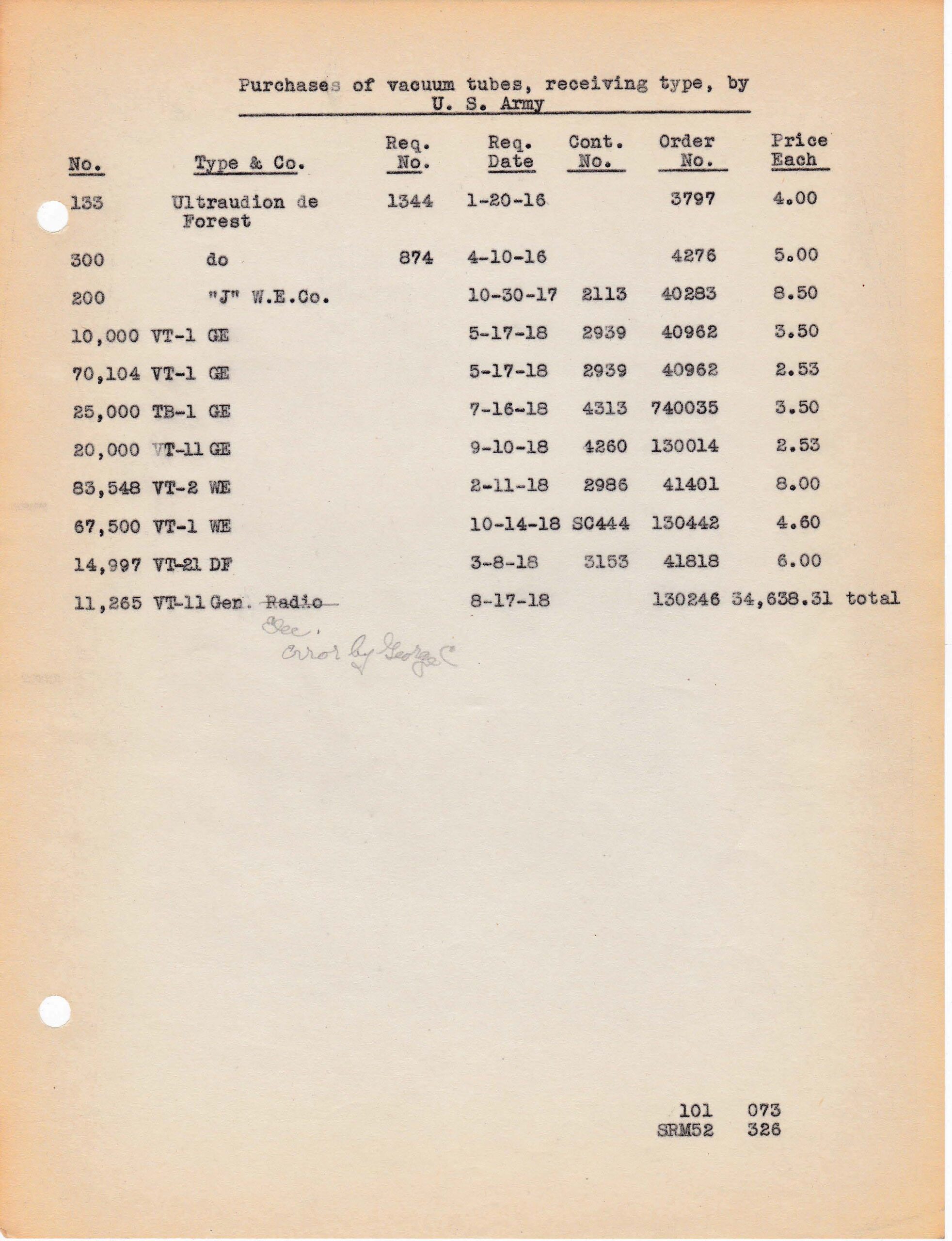
Fig. 15 shows the pin locations, now changed from the CG 886. A more standard 4 pin design, mica base to hold same and the wire from the base soldered to one pin. The reason for the mica and wire to the pin is unknown at this time.
Fig. 16 is a tube from the Tyne- Vanicek collection and is a second example of the VT-1 is shown in fig. 13. The paper tag states that it is a VT-1- early VT-11 and the year 1918, receiving type used as an amplifier, detector and oscillator similar to samples manufactured for the Army Signal Corps. by GE. This tube has VT-1 on the press as well. The paper tag was probably made and taped on the tube by William White and placed in the GE tube museum in Schenectady, NY. [8]. The base, bulb shape and internal construction matches the VT-1 in fig. 13 exactly including the wire from the base to one filament pin that was subsequently broken off.-, although the Mica has been eliminated to the more familar G.E. ceramic incert to hold the pins.
It is confirmed, by the document in Fig. 17, that the first tubes to be manufactured by G.E. for the WW1 war effort were designated VT-1, NX4 shown in fig. 13 -15. This paragraph is a scan from the book “The National in the World War” written and published by the General Electric Company in 1918. [7]
The document above, Fig. 18, is one of many scans this authors made of the copied papers Tyne made from the historical files George Clark abstracted on Sept. 15th, 1938 that appear to be compiled for a court case. It involved the Fleming Patent, Marconi WT Co. of America, plaintiff, VS. de Forest T&T Co. of Audion bulbs and equipment sales up to Feb. 27th, 1919. The fact that the GE tubes sold is included seems to be just a coincidence. It shows the receiving tube types purchased by the US Army. Considering the lack of examples of the GE VT-1 that have survived, it is difficult to imagine that more than eighty thousand were ordered, produced and purchased. It is more likely that GE produced a small number of VT-1’s when improvements were made and the remaining tubes produced were then designated VT-11.
Some types, dates and numbers also conflict with the William C. White paper entitled “The Story of Electronics Development at the General Electric Company”. He states that the US Signal Corps “ordered 80,000 tubes they called the VT-11 in 1913”. [12]. Overlooking the fact that the 80,000 tubes purchased are VT-1’s in the document, the numbers somewhat match assuming only a few VT-1’s were purchased when the name switched to VT-11. Perhaps White meant the VT-1’s or VT-11’s were ordered in 1918. This is more likely. Now the dates match and the only mystery left is the VT-1 – NX4 itself and the quantity GE actually produced. Some purchases of the VT-1 and VT-11 may have been cancelled which could explain some of the number differences. Coincidently, the Clark papers contain the only document ever found by the authors that even mentions the GE VT-1. Clearly, more information needs to be found but it seems quite clear to the authors. [13]
The very familar early W.E. type J is shown in fig. 19 with its son, the early W.E. VT-1. The two Western Electric tubes in Fig.’s 19 and 20 are very good examples for meeting engineering military specs in totally different ways, keeping in mind they were direct replacements for the General Electric VT-1’s (VT11’s) in many WW1 radios in figures 12-16.
Notice the type J in fig. 19 has a glass arbor to support all the top elements and this expensive process was eliminated in the VT-1 in fig. 20.
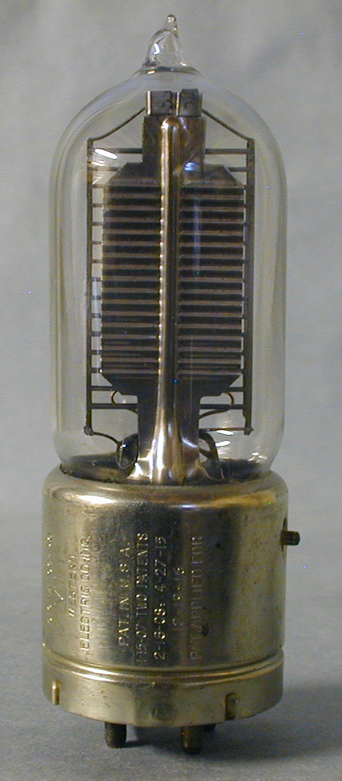
During the manufacture of the VT-1- NX4, it appears that more improvements were made and confusion averted with the W.E.VT-1 by the G.E. renaming it the VT 11, shown in Fig. 21. [13] and the shipping box in fig. 22. The tube would have been marked VT-11 on the press and be shipped to the US Signal Corps. The VT- 11 tubes were now equipped with a porcelain insert to hold the 4 pins. Notice the similarities in the internal design with the tubes in Fig.’s 5, -16. The VT-11 Signal Corps tubes were to be used as amplifiers, detectors and oscillators in the same equipment that used the Western Electric VT-1 tubes. Tyne quote regarding the General Electric VT-11 and Western Electric VT-1- “No more forcible illustration could be made to bring out the point that each company brought to the field of development of the vacuum tube its own particular back round of experience gained through trying to solve its own problems in other fields. The scientists and engineers of these two companies who sought answers to the same questions had, because of experience, taken different paths to arrive at a common destination”. [11]
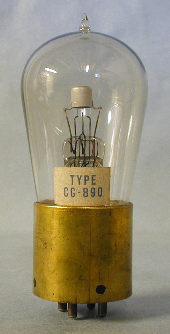
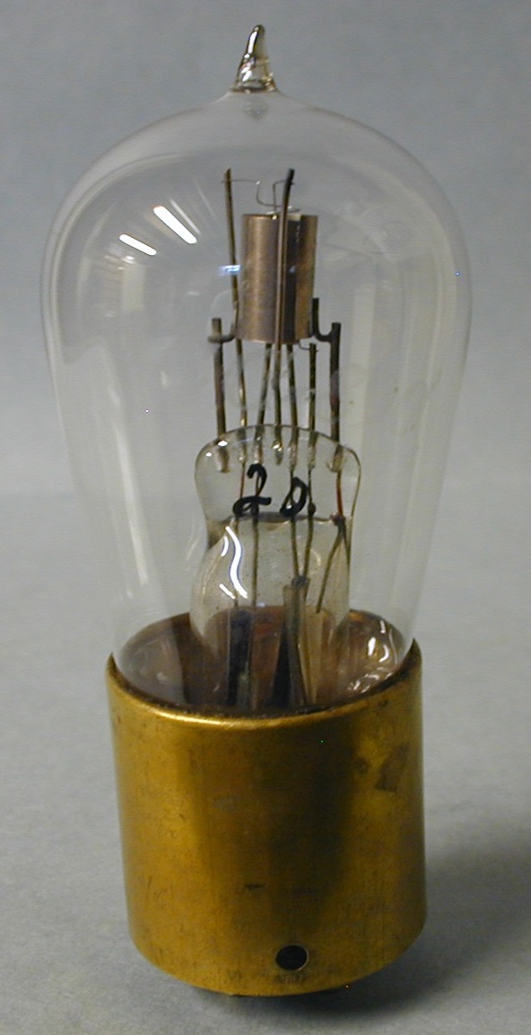
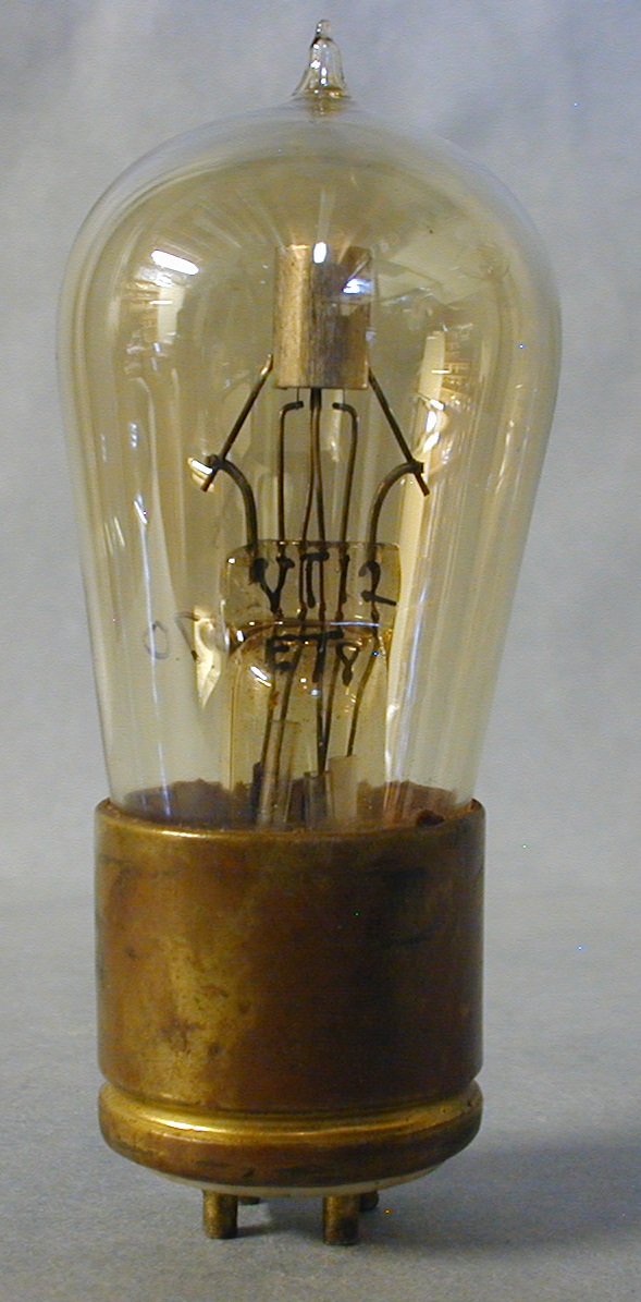
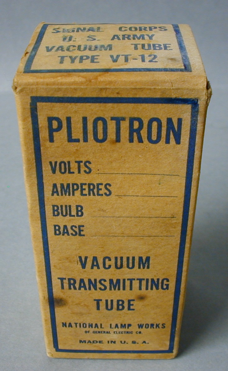
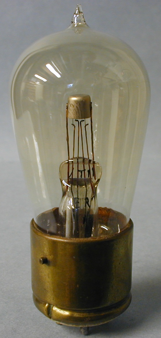
Fig. 23. Improvements were made to the Signal Corps VT-11 in fig. 21 but the US Navy re-named it CG890 as can be seen on the paper tag and the VT-11 was retained as a name by the Corps. It could, then, be shipped to the Navy or the Corps with the proper names. Improvements were a more rugged structure and voltages.
The tube in fig. 24 shows more improvements made to make it more rugged for the Navy use. To avoid confusion, CG 890 was now etched on the glass bulb and the number 20 on the press that re-placed the VT-11. For reasons unknown, however, a brass band fron the base to one pin in the base was carried over from the initial design shown in fig. 15 on the CG890 and the new design in fig. 24.
Fig. 25. In early 1918, the US Signal Corps put in an order for transmitting tubes G. E. designed and called the type T pliotron, named VT-12 by the Signal Corps shown in Fig. 25. The VT-12 was a low power oscillator used for wireless telephony in aircraft transmitters. The VT-12 was made to be used in transmitting sets that also used the Western Electric VT-2. [14]. Like the W.E. VT-2, the VT-12 has the side pin in line with one of the bottom pins. The base has a porcelain insert to hold and insulate the pins. Tyne’s “Saga” calls the tube shown in Fig. 8-21 on page 150 the VT-12. This seems to be an editing error as the VT-12 is actually shown in Fig. 8-22 on page 151. The VT-12 was introduced so late in WW1 that very few were received in France beffore the war ended. The base now has a porcelain insert to hold and insulate the pins.
Fig. 26 shows the shipping box for the VT-12
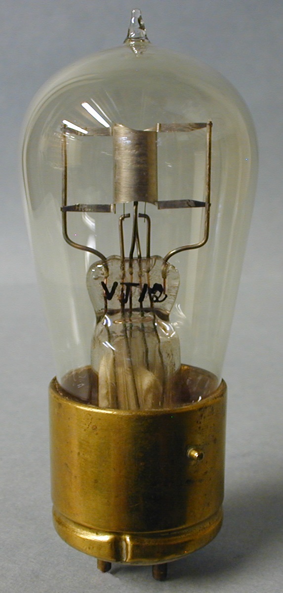
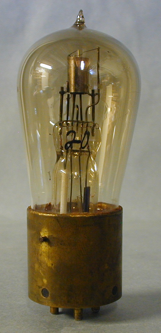
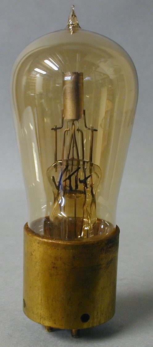
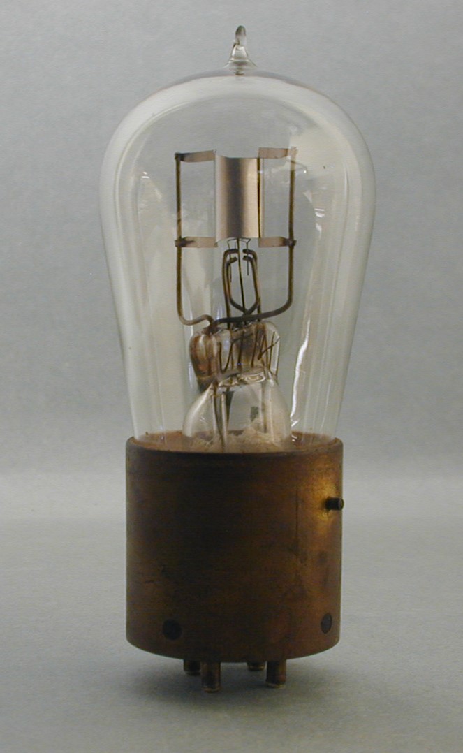
Fig. 27 is a another improverd version of the VT-12 transmitting tube. The plate inner structure is most like the first versions of the TB-1 regulating tube and the Navy CG 1162 transmitting tubes.
Fig. 28 shows the VT-13. General Electric soon redesigned and improved the VT-11 and CG-890 receiving tubes to improve their ruggedness and radio characteristics. [15]. The Navy retained the CG- 890 designation while the Signal Corps renamed it the VT-13. The VT-13 were to be used as amplifiers, detectors and oscillators like the VT-11 and perhaps as a better replacement to the W.E. VT-1. [16]. The tube shown has 20 on the press. What the 20 signifies is unknown at this time but the same type tube is shown in fig. 8-20, page 150 in the Tyne book that also shows 20 on the press. Some examples may have VT-13 on the bulb or press but none have been observed. A total of around 5000 of both types of the CG-890 and VT-13 tubes were delivered to the US Military at about the time WW 1 ended in 1918. Most observed have gold contacts on the pin bottoms for a good contact. This tube must have been a bit confusing as VT-13, VT-11, CG 890 are not shown on the glass or press and only 20 on that press.
Fig. 29 shows the VT-14, early design, with an improved structure of the VT-12 transmitting tube in fig. 25. The newly designed tube was numbered CG-1162 by the Navy and called VT-14 by the Signal Corps and is shown in Fig. 22. [17]. This tube has CG-1162 etched on the glass bulb and VT-14 on the press. Like the VT -12, the VT-14 was a transmitting tube that was to be used on sets that used the W.E. VT-2 and had the side pin aligned with one bottom pin as on the VT-2. Fig. 8-21 on page 150 in Tyne’s book calls the tube shown the VT-12. This appears to be an editing error. The tube shown seems to be the CG-1162.
The tube, VT-14 later design, in fig. 30 is yet another improvement in the radio and inner design of the VT-12. It does have VT-14 on the press to help with identification.
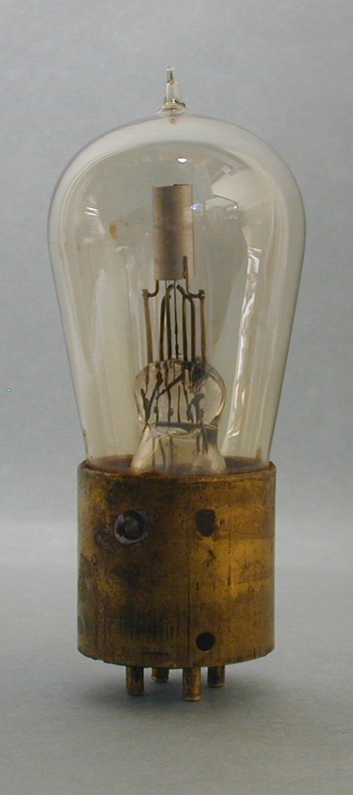
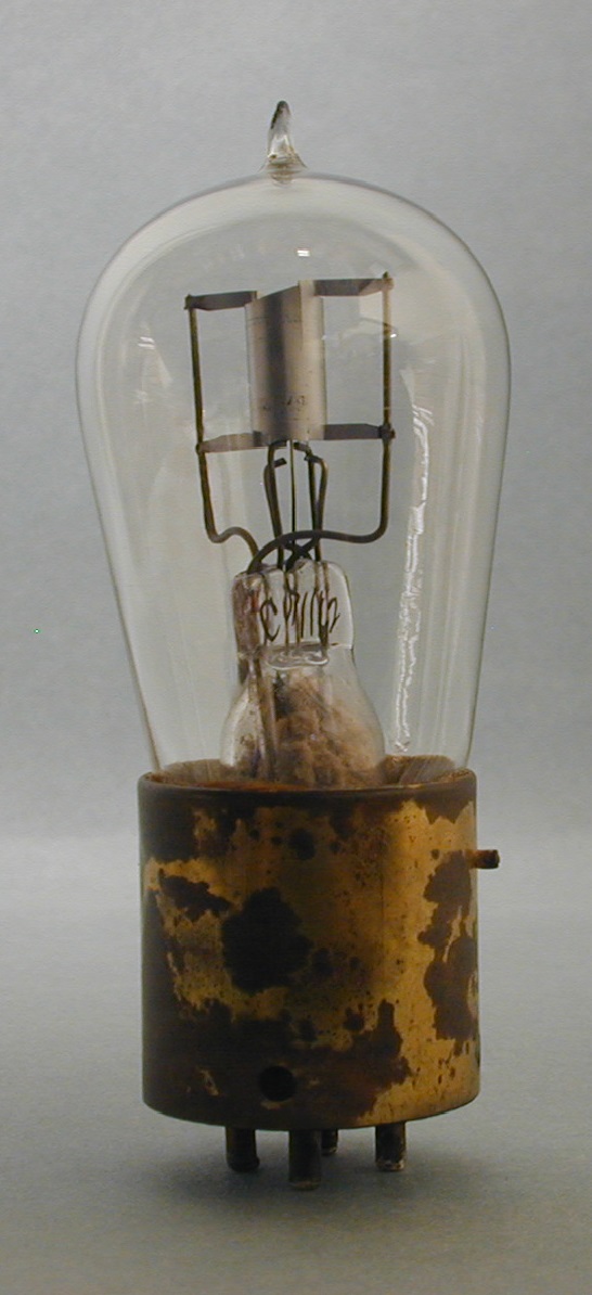
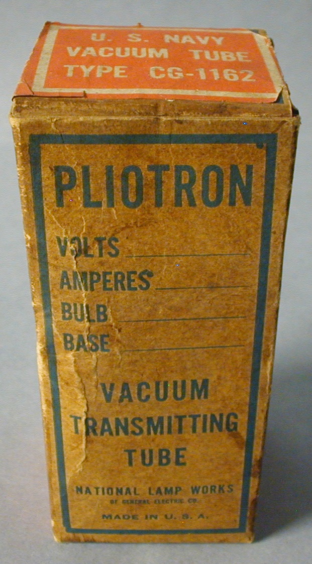
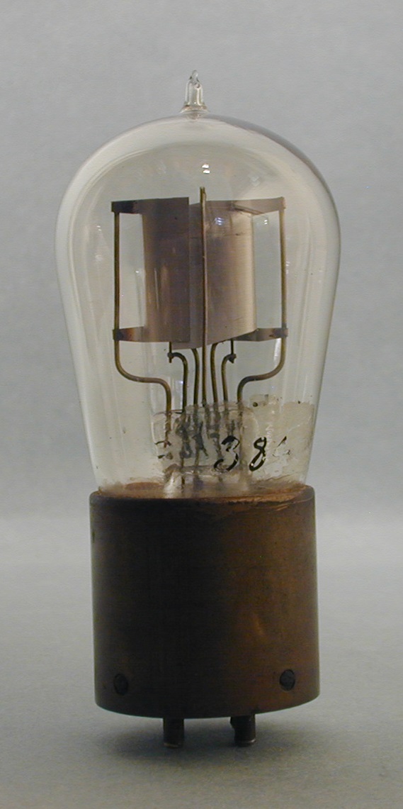
Fig. 31. early VT-14. The CG-1162 and VT-14 tubes had gold soldered on the pin tips for good contact. Many of these types have had the gold removed and the side pin relocated so they could be used in standard sockets. Tyne quote. “It is interesting to note that many of these tubes were used by amateurs as Barkhausen oscillators in the earlier days of amateur activity at ultra-high frequencies, after they had appeared on the salvage market”. [18]. This explains the pin changes. This is the case with this tube. As can be seen, the dark spot to the left on the base is where the pin was located. To the right is where the pin was re-located to for use in a Barkhausen oscillator.
Fig. 32. This is the CG 1162, the Navy name for the Signal Corps VT-14. It has CG 1162 on both the press and the glass bulb. [19]
Fig. 33 is the shipping box for the CG 1162 transmitting tube.
Fig. 34 shows another improvement in the design of the CG 1162 and probably the final one. It looks much like the G.E. OO’s in the structure. The other number obscuring the number on the press is part of Tyne’s numbering system.
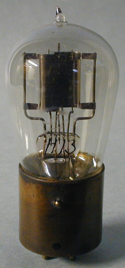
Fig. 35. General Electric soon developed a new transmitting tube working to improve the VT-14. Two versions of the General Electric designed transmitting tube the Signal Corps called the VT-16 were designed to improve the ruggedness for use in airplane service and were in the developmental stage towards the end of WW1. [20].
Fig. 36. The internal design has been carried forward from the VT-16 to the new G.E. UV-200. Note those similarities in the early G. E. UV-200 with a Shaw base in Fig. 35. To find an early G.E. UV 200 tube with a Shaw base was quite hard. As with many of these early G.E. experimental and production tubes, the Shaw standard bases were purchased from the closing sales of the Moorhead Laboratories and his companies that followed and the De Forest and Marconi logos that were pressed into the bases were ground off. Just enough of what remains can be seen.
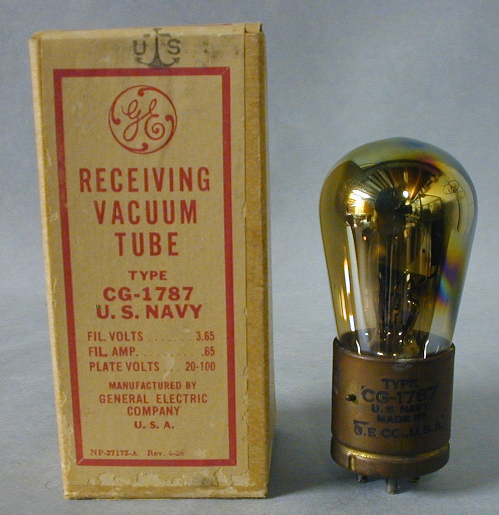
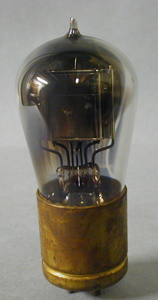
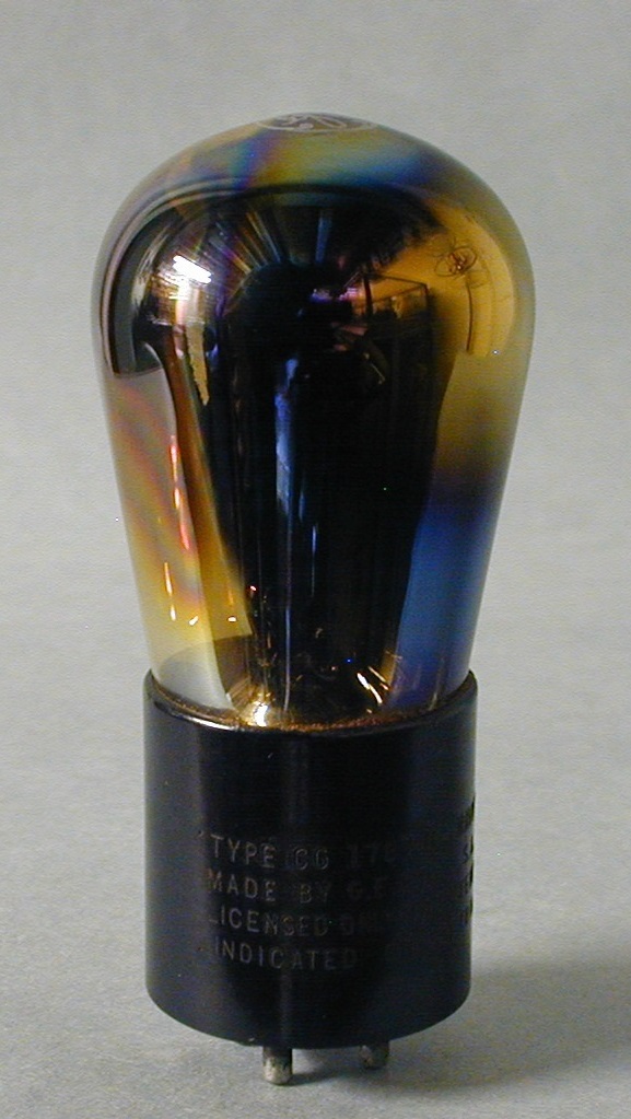
Fig. 37. The CG 1787, shown with its shipping box, receiving tube was developed before the end of WW1 but released after. The getter used was phosphorus which gives it the rainbow effect. The inked base shows the full name, for whom it was made, in this case the US Navy and the maker- G.E. Bulb is machine made.
Fig. 38. The very same tube without the phosphorus getter but now the inked horizontal information is simply stating CG 1787. Again, released after the war ended with a hand blown bulb.
Fig. 39. The CG 1787 with a machine made bulb, phosphorus getter and bakelits base with the info burned into the base. Released after the war.
Fig. 40. The TB-1 rectifier/ regulator, used in wind driven generators, was made just before the wars end and continued after. This tube has the standard Shaw base but later tubes had the standard G.E. base. It had a special 3 pin base and had to be built to withstand the obvious vibrations given off by the propeller.
Footnotes:
Numbers between brackets refer to the references below.
All tubes pictured are from the Gruber collection except those in figures 2, 5, 6, 7, 13 and the document in fig. 18. Those reside, or did, in the Vanicek collection.
George Clark devised the numbering system for the US Navy. Before the type number was a letter designation indicating the source: SE (Bureau of Steam Engineering) for a Navel design and C if a commercial design followed by one or two more letters indicating the particular number given. Therefore CG-886 would be Commercial – General Electric – type number 886. [21]. Click on the hyperlinks NS below in [21] to view George Clarks US Navy numbering system and CEB for the correction made by Bob Palmer that appeared in the AWA review at some point later.
- [1]White, W. C.“The Story of Electronics Development at the General Electric Company”,page 22
- [2]as [1]
- [3]Vanicek, J. Conversation regarding the Pliotron in Fig. 1.
- [4]Vanicek conversation with Howard Schrader regarding his acquisition of similar accession numbered prototypes from William White held at the G.E. Museum at that time.
- [5] Anderson, J. M. “A Sketch of Early Radio Vacuum-Tube Research and Development at the General Electric Company” from the Antique Wireless Association Review #4, 1989. page 24. Used with the permission of the AWA via Robert Hobday.
- [6] as [5], pages 23, 24
- [7] General Electric Company, book, “The National in the World War, April 6th, 1917- November 11th, 1918”, between pages 242 and 243, center photo and conversation with Jerry Vanicek regarding this tube in his collection.
- [8] Vanicek, J., tube in Vanicek collection and conversation about the internal structures.
- [9] as [7], page 242.
- [10] General Electric Company, book, “The National in the World War, April 6th, 1917- November 11th, 1918”, page 237.
- [11] Tyne, Gerald “Saga of the Vacuum Tube”, 1977, page 154.
- [12] as [1].
- [13] The conclusions in this sentence and the entire description presented are assumed to be correct based on the information shown in fig. 13, 15, and 10. Tyne papers in the Vanicek collection.
- [14] as [11], page 154.
- [15] as [14].
- [16] White, W. C. “The Development of the General Electric Company of Radio Receiving Tubes”. page 11.
- [17] Tyne, Gerald “Saga of the Vacuum Tube”, page 149.
- [18] as [17], page 150.
- [19] as [9], page 243.
- [20] as [1], page 23.
- [21] Howeth, Captain L. S., “History of Communications-Electronics in the United States Navy”, 1963, pages 218, 219, 576. numbering system by Clark: See here: NS
- Corrections by Bob Palmer to NS above here: CEB3
Leave a Reply