

Identification of the Radio Equipment used on the NC-4
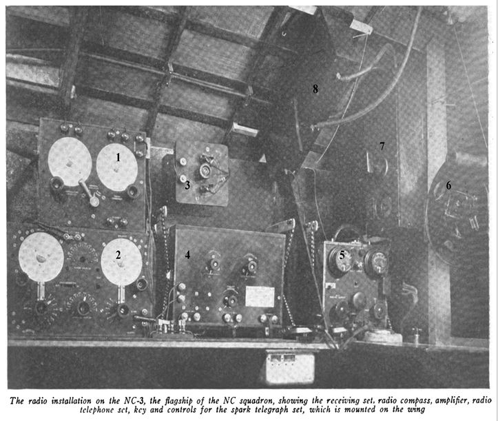
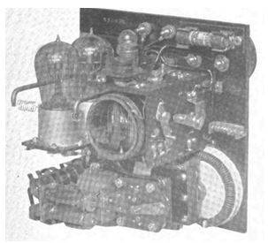
The initial article in the May 2016 TCA magazine on the flight of the NC-4 contained this picture, fig.1, of the radio equipment that held the vacuum tubes that made the first trans-Atlantic crossing possible. This author felt compelled to identify the devices used. They are numbered 1-8 as can be seen in the half-tone photo taken on the NC-3. It is, however, not known when the photo was taken, before or after the flight as they made many last minute changes just before the actual flight.
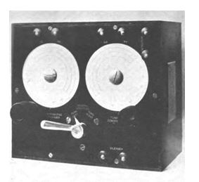
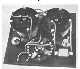
Fig. 2. The devise that is numbered 1 is the SE 1441-A radio compass controller. When the radio was used as an amplifier (number 4) in conjunction with the compass system, it was necessary to employ this devise. The radio compass was used to determine the accuracy of the flight path with the US Navy ships below on the ocean surface. This was switched off when using the amplifier to communicate directly with those ships with the secondary tube transmitter or the primary wind driven spark gap transmitter. The pictures in figs. 2 and interior of #3 are US Navy contemporary photos of the controller. The SE letters indicate it was a Navy design. It appears to have been made by the National Electrical Supply Co.
Fig. 3 is the interior view of the SE 1441 compass in fig. 2
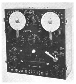
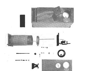
#2. Devise numbered # 2 is the first standard radio the Navy made, the SE 950. The original layout of the SE 950 is shown in figs. 4 and interior of same in fig. 5. When the radio in fig. 4 is compared with the NC 4 picture it is obviously much larger. A special version of the SE 950 was made omitting the bottom half of the amplifying compass section of that radio and then installed on the NC-4. That section would have contained 3 Western Electric VT 1 tubes. The NC 4 radio designers concluded that they would use the top half of the 950, the tuning half alone and use the Moorhead SE 1444 tubes in another special section to amplify the signals. All the radio equipment used on the NC expedition was designed by the Radio Test Shop, Navy Yard, Washington, DC. The National Electrical Supply Co. made the original SE 950 from those Navy designs. The special version was probably altered by the Navy Radio Test Shop but this is just a guess by the author as it may have been done by the National Co. Fig. 5 shows the inside of the SE 950.
#3. The devise that is numbered 3 is a bit of a mystery. No picture could be found but just a written description possibility but it appears to be a variable condenser probably used with the 6 stage amp (number 4). It looks to be Navy built. Another guess would be a gyroscope of some sort, possibly added at the last minute for some reason.
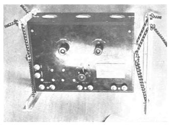
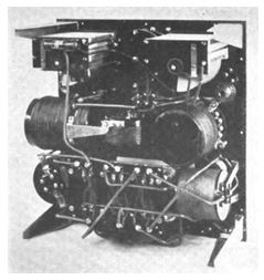
#4. Fig. 6. The number 4 devise is a three-stage radio frequency amplifier used on the NC- 4 and could be used in conjunction with the radio compass amplifier or standard radio receiver-amplifier. This was made by General Electric. The amp in the Navy photo in fig. 6 appears to be identical. Its circuits used three stages of RF amplification, one detector and 2 stages of AF amplification. All six tubes used in this amplifier were of the Moorhead SE 1444 type. When used as an amplifier as a compass it was known as the 1605-B unit and when used as a standard receiver amplifier it was known as the SE 1405-B. It was made by General Electric to the Navy Radio Test Shop specs. As can be seen in fig.6, the entire cabinet was suspended by an elastic cord system to prevent vibration.
Fig. 7 is the interior look of fig. 6.
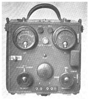
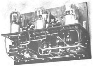
#5., fig. 8. The devise numbered 5 presents another mystery. This set appears to be a version of the CG 1104 or CG 1104-A secondary transmitting set. The Navy picture in fig. 8 looks to be close to the devise numbered 5 in fig. 1. The vacuum tubes in the fig. 9, back view of this same transmitting set shown in fig. 8 appear to be the Navy CG 1162 tubes. This is contrary to the General Electric claim that the CG 1144 transmitting tubes were used on the NC planes. It is possible that the photo in fig. 1 was taken before the flight and that a different unit was actually used, perhaps on all planes or only on the NC 4. A transmitter using CG 1144 tubes may have been placed on the NC planes just before the flight. Only this speculation explains the GE claims CG 1144 tubes were used on the NC 4. In any case, the NC 3 removed the secondary transmitter, perhaps shown in fig. 8 because of weight. It also meant that the dyna-motor and the 2 12 volt wet cell batteries used to power that motor could be eliminated. This came back to haunt the NC 3 when it was forced to land on the water and without the wind to turn the blades on the primary spark gap the plane could only receive messages. It was a matter of luck that a ship spotted them and they were saved.
#6. The devise numbered 6 is the reel to hold the wire for the trailing antenna. The wire could be released and then wound back onto this spool. This was the most effective antenna but when the planes were on the water surface, the blades on the primary spark gap generator did not turn. The secondary communication vacuum tube driven transmitter then used what was called the skid fin antenna, mounted on the wing. This was quite limited in comparison.
#7. The devise numbered 7 that is mounted on the bulkhead near the antenna reel is the variometer assembly for the primary wind driven spark transmitter mounted above on the wing. A typical variometer assembly is shown in fig. 10.
#8. The devise numbered 8 is the send-receive switch for the spark gap generator contained inside the wind driven generator shown in fig. 11 and 12. Two flame proof keys can barely be seen in the picture in fig. 1 between the amp and transmitter- the 4 and 5 devises. One or both of those probably contained an in use glowing lamp. One key was used for the spark gap and one for the vacuum tube transmitter. The pilot would have had one as well to communicate.
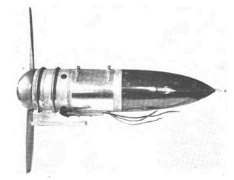
Fig. 11 is a Navy picture of the wind driven generator used on the NC-4. This generator could not only supply needed power on the plane but also contained and powered the spark gap, the primary pieces of equipment that the radio operator used to communicate. The GE tube TB-1 was used as a regulator in the generator and was situated inside the bullet-shaped end cover.
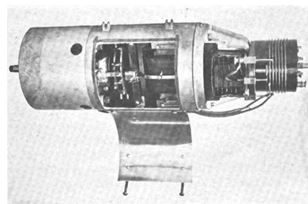
Fig. 12 is the generator with the end cap and inspection hatches removed and open. The entire generator was manufactured by the International Radio Telegraph Co.
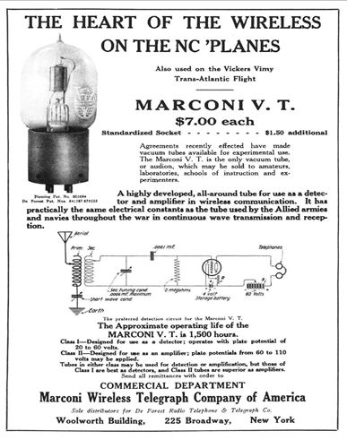
Fig. 13 is an ad for the Marconi VT from 1920, just after the flight. It is actually the very same as the Moorhead SE 1444 used on the NC-4 flight.
Sources:
- Denby, Edwin, Secretary of the Navy, “History of the Bureau of Engineering Navy Department During the World War”, Publication Number 5.
- Johnson, T, Jr, Navel Aircraft Radio. Expert Radio Aid, Navy Department, Washington, DC. Paper written for the IRE, 1920
- Kinney, E. M., Radio Apparatus for Aircraft and Ground Stations, Proceedings of the Engineers’ Society of Western Pennsylvania, 1921.
Leave a Reply