

Contrary to popular belief, Robert Von Lieben, was the first to design and patent a triode amplifier valve. His triode amplifier patent, numbered 179,807, was published on Nov., 18th, 1906 in Germany. By contrast, DeForest had a working audion triode in his lab on Dec., 30th, 1906. He filed for a patent on Jan., 29th, 1907. Lee DeForest’s Audion triode patent, numbered 879,532, was issued on Feb., 18th, 1908. He filed for a patent on Jan., 29th, 1907. The entire world electron-tube industry was a result of the 1912-1920 Von Lieben mercury-vapor triode, Western Electric/General Electric vacuum triode, and the French Military TM high vacuum triode. It must be noted, however, that Von Lieben and DeForest goals with their tubes and patents were much different. Von Lieben had no contact with wireless, only telephony and telegraphy, and thusly was only interested in amplification. DeForest on the other hand was interested in wireless in all its uses. In other words, amplification and detection.
Without the aid of an example of the tube in this authors collection, I will briefly explain the history of this first known triode.
Robert Von Lieben was born in Austria on Sept., 5th, 1878 and died Feb., 30th, 1913. More about his death later. Robert was born to wealthy parents and this afforded him to pursue his interests in technical topics and experiments. His interest in things scientific came from his uncle Adolf, then a distinguished chemist at the University of Vienna. Another uncle, Richard, also contributed to the financial interests of the family. Around this time, he volunteered for military service. In a riding accident, after he was thrown from his horse onto a fence, he suffered a punctured lung that never healed properly. This was to change his life and cut it short in his prime at the age of 35. His scientific interests were much more important to him than his high school studies and he never did graduate or obtain a physics engineering degree and never took a final exam. It could be said he was more or less an independent scholar working in the laboratory his father paid for. He devoted himself to studies that involved gas discharge and electron beams. This involved attending physics lectures at the University of Vienna. At this time, he also gained practical experience with manual work at Siemens in Nurnburg and added courses in experimental physics in Vienna.
In 1899, Lieben attended the University in Gottingen for a year of study under the brilliant professor Walter Nernst. They became fast friends and this would have a profound effect on Lieben. In 1903, Lieben published a paper concerning the polarization of X-rays. These studies set him up with the necessary experiences with the phenomena of discharges of gas with cathode rays that would serve him well later in developing his telephone relay and radio amplifier.
Click all pictures for a larger view
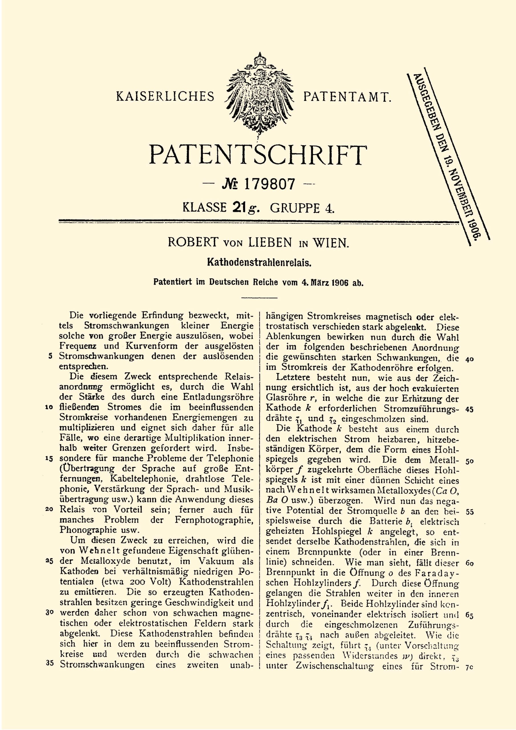

Figs. 1, 2, and3 is the first Von Lieben patent mentioned in the first paragraph above, 179807. It is in German so a brief explanation in in order. This patent was for his Cathode Ray Relay. The electron beam from below was deflected upwards by a magnetic coil and indentified by the letter e in fig. 3. The whole prototype valve was as tall as a man and was connected to a vacuum pump, as good as could be had in those early days, at all times to get the desired effect. The patent goes on to secure the rights to the electrostatic control of the electron beam in a vacuum. The patent also controlled the rights to the full range of frequencies. The valve did amplify, however, and this was confirmed by Walther Nernst. Although, technically speaking, the valve was far from perfect and made it obvious that further development was necessary.
At this point, Lieben enlisted the help of 2 of his fellow students at the University of Vienna, Eugen Reisz and Siegmund Strauss and became the co-owners of all the subsequent patents. The name of the new valve being named LRS. Building on their own work and others, Reisz went on to invent the carbon microphone and Straus, annoyed by the whistling on early telephone lines, discovered it was feedback from the transmitters. Dr. Richard Leiser was also involved with the team in his studies of the chemistry of cathodes and his contributions involved a longer-lived oxide coating on the filament. but left the team shortly after the initial help.

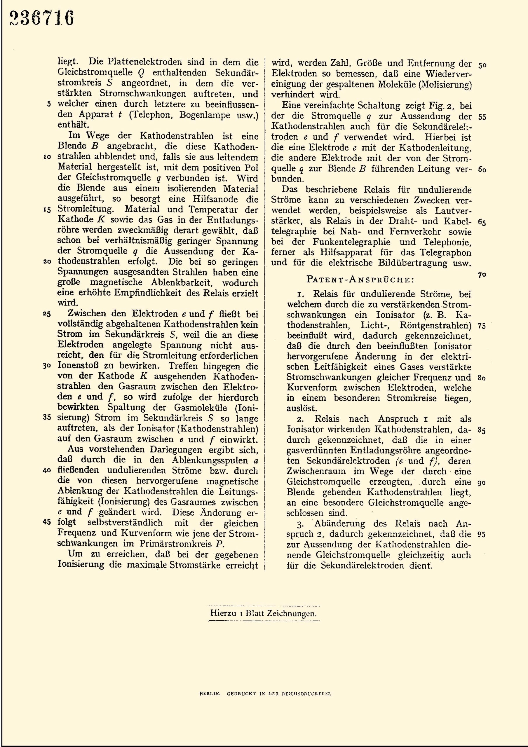
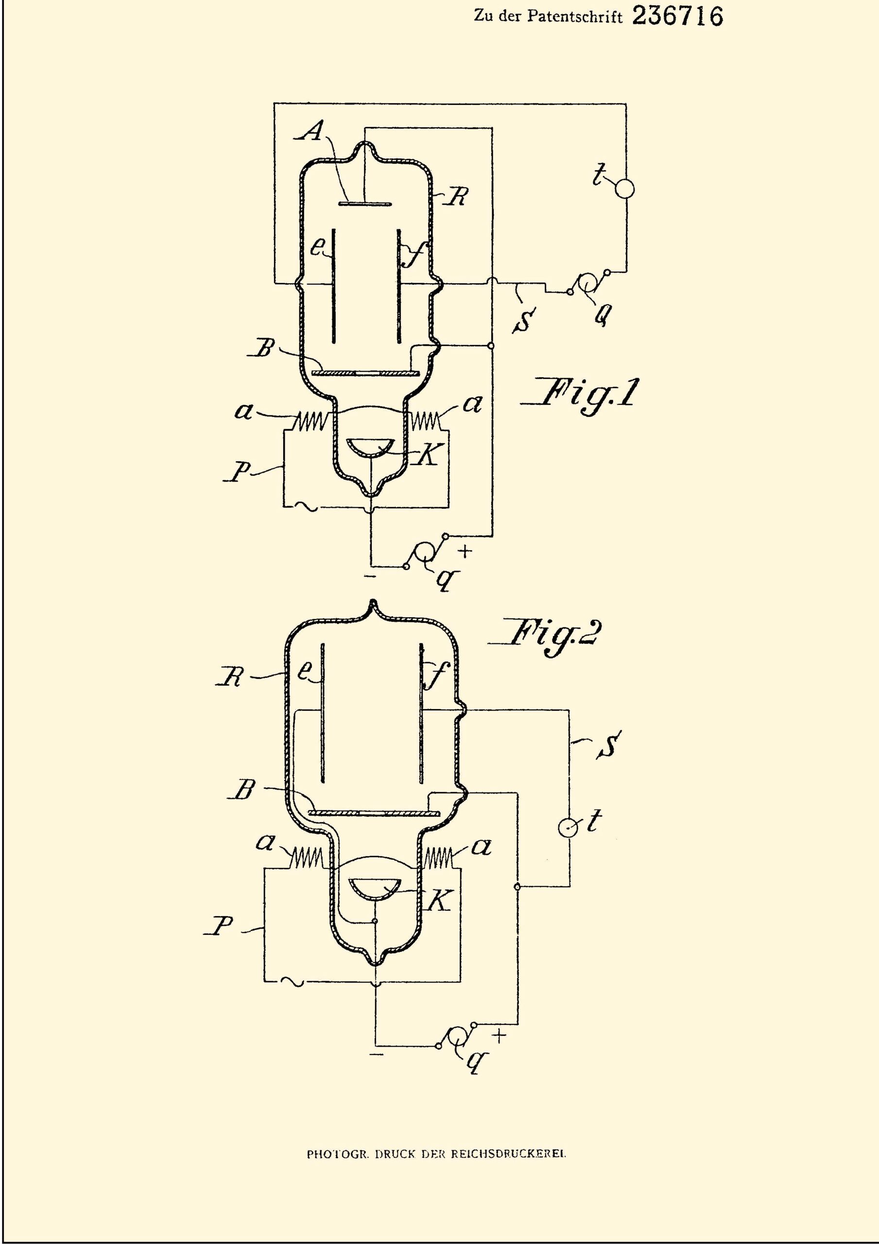
4 years later in 1910, the further valve improvements produced 2 new patents, patent number DRP236716(relay for undulating currents), figs. 4, 5, and 6 above, in which an ionizer is influenced by the current fluctuations to be amplified) and an additional patent number DRP249142(the so-called grid patent). Patent DRP236716 shows the new developments from Liebens original patent.


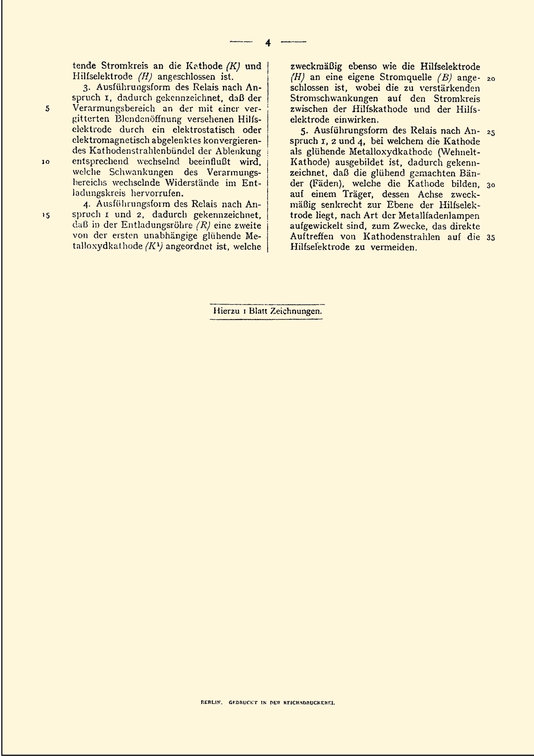
Patent DRP249142, shown above in figs. 7, 8, 9, 10, and 11,(external magnets are gone and the beam is now controlled electrostatically) shows a completely new tube with a grid between the cathode and the anode as first used by DeForest. DeForest did not use the grid to control the electron beam, but to suppress glow light at the anode, and, therefore, DeForest’s triode was not an amplifier tube, but an improved detector diode. Lieben used the grid to control the density of the electron beam and thus achieved an amplifier effect. Lieben only thought of an amplifier effect and DeForest only thought of radio reception. Fig. 11 shows the first grid-controlled Lieben valve. There was a year-long legal dispute that was decided in Liebens’ favor. Lieben’s health continued to deteriorate from his military injury mentioned above and this would apply some pressure on Reisz and Strauss to complete the improvements on the LRS amplifying valve. To add to Lieben’s health problems, it could be said that Lieben was always interested in the pure-science aspects of his relay rather than a commercialization of the valve. Reisz and Strauss to steer him in the direction of a product which might give a financial return. To this end, Reisz and Strauss tried to attract large German companies to invest to the final design;. More on this shortly. Great aspects to this attraction of companies were the facts that the valve operated as planned giving very good amplification, with long life, more valves could be made with much assurance of success.
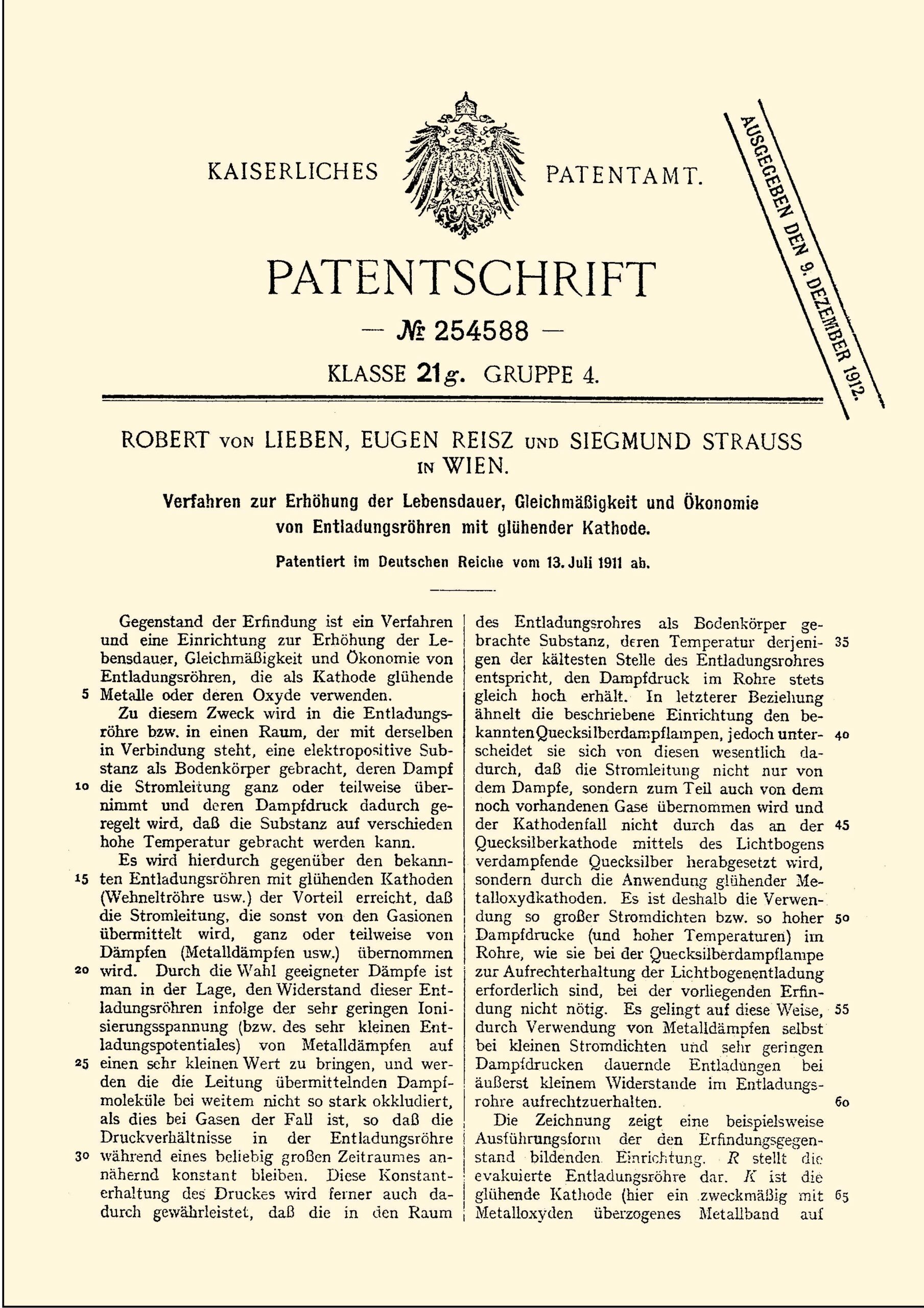
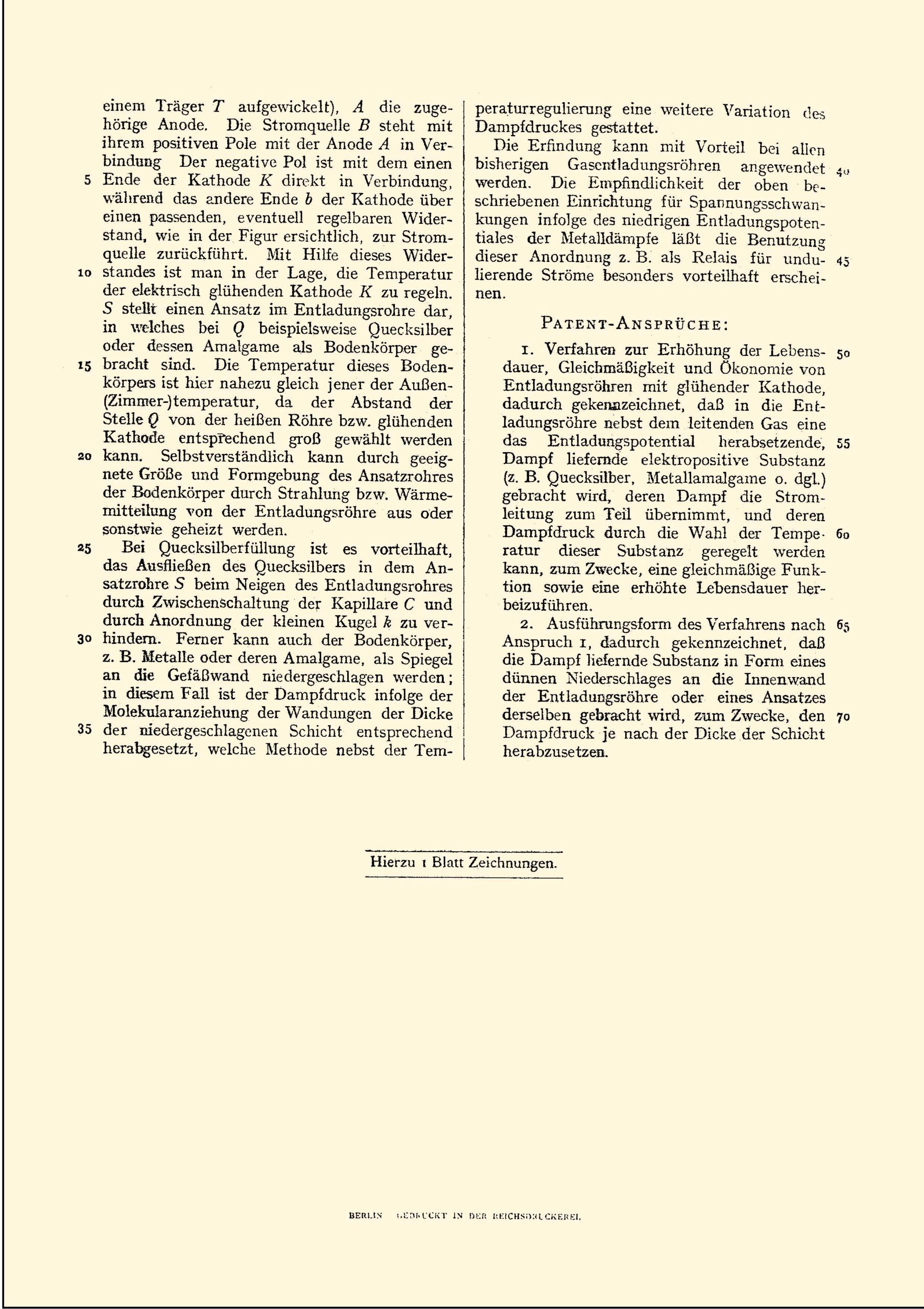
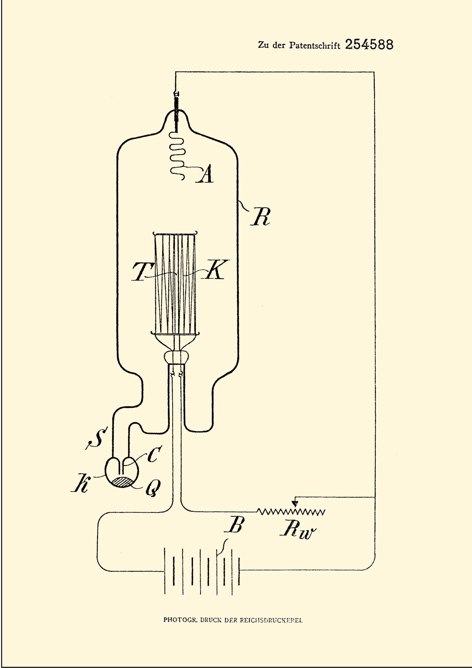
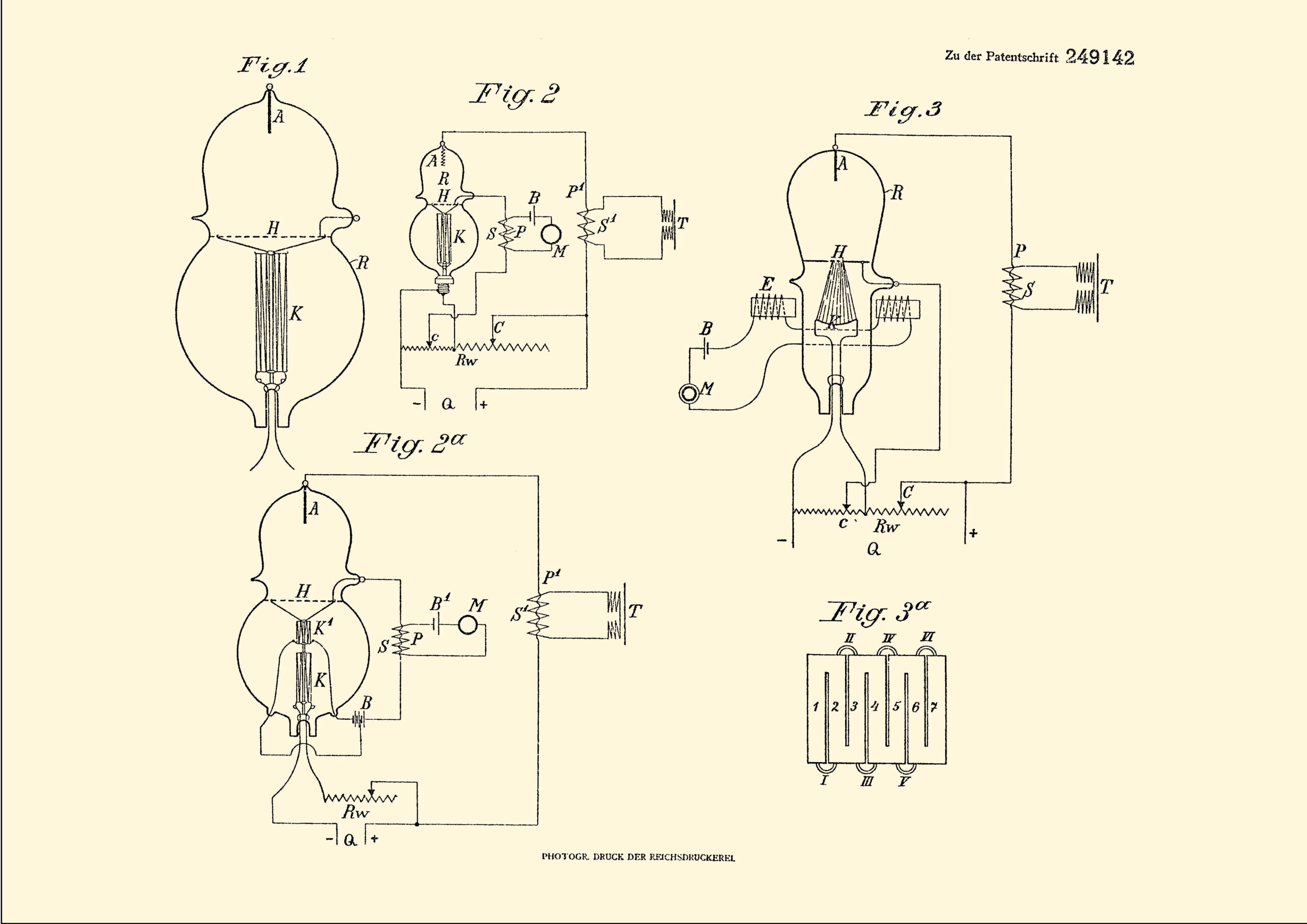
In July, 1911, Lieben, Reisz, and Strauss applied for a new patent, 254,588, shown in figs. 12, 13,and 14. This was a clean-up patent to improve the life, economy of discharge with incandecent cathodes. These improvements now made the valve ready for marketing. 1 Month later, a demonstration was given to the German companies: AEG, Telefunken, and Felton und Guilleaume(TeeKaDe), probably set up by Nernst. By this time, Lieben was becoming quite ill was less and less involved with research and valve improvements. Nevertheless, improvements carried on by Reisz and Strauss and the interested consortium, now including Siemens und Halske AG. Their sights expanded to not only filling large spaces with very adequate sound but with long-distance communication, detection, radio equipment containing improved electron valves. An agreement was necessary to exploit the Lieben patents and this was done on Feb., 19, 1912. Reisz and Strauss continued the necessary research, along with the best the consortium could provide, at the laboratory at AEG.
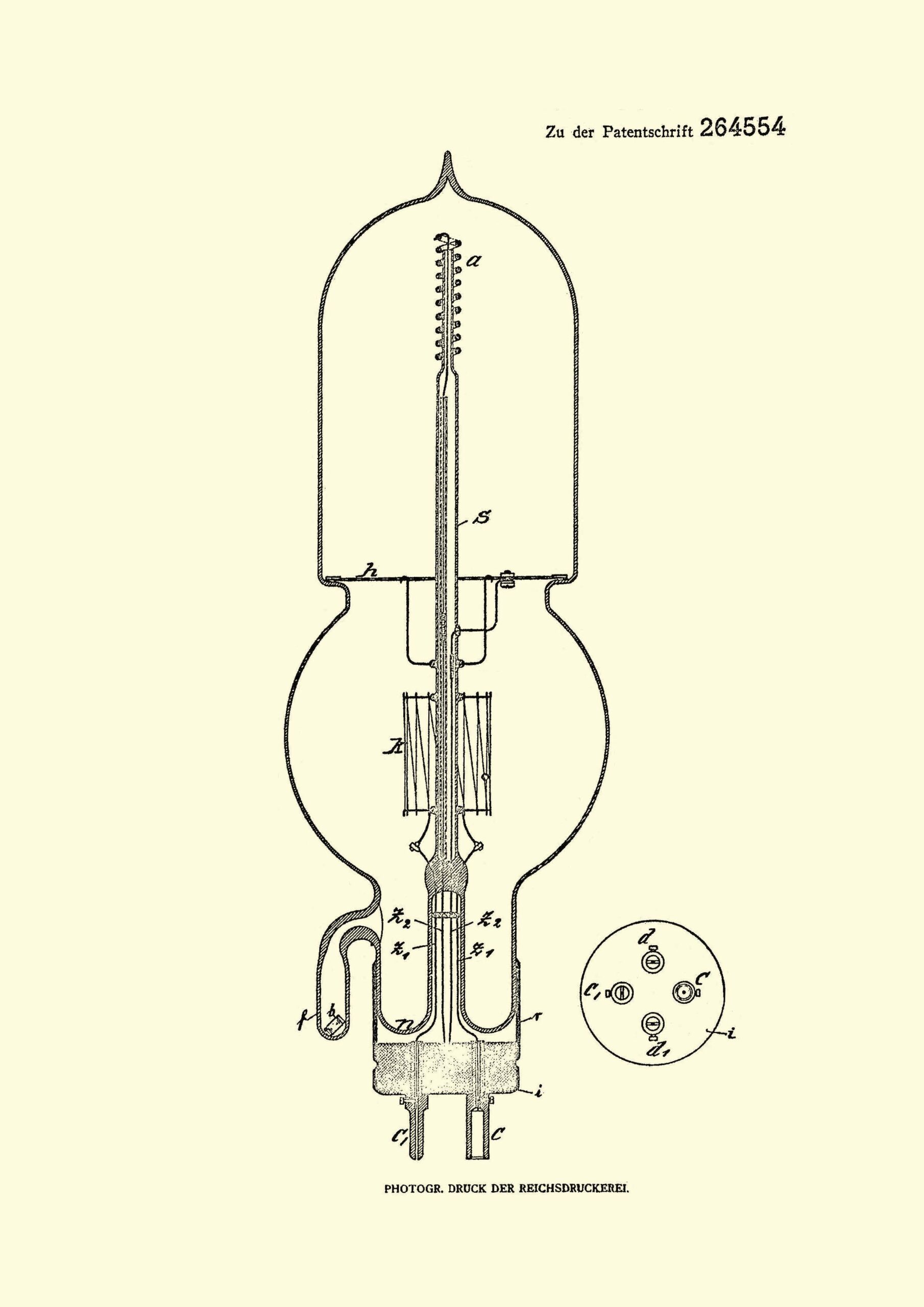
A few problems arose: Siemens found that mercury, added to all Lieben tubes heated to a mercury vapor, was inherently noisy and maintenance of such vapor would be impossible. Work at GE using an improved Gaede vacuum pump seemed to indicate that perhaps this could be used to make a high-vacuum LRS. The original LRS continued to be worked on while other members of the consortium concentrated on a high vacuum version of the valve. Fortunately, the Gaede pump was held in German patents which allowed easy and quick access to what was required to create a hard version of the LRS valve. The Gaede vacuum pump allowed the final form of the LRS tube to be much smaller and aided in its final form shown below. Some final changes were made by the consortium are shown in patent number 264554 in figs. 15, 16, and 17 in late 1912. Looking at patent pictures in figs. 14 and 17 it can be seen that the filament height has been reduced, a rod supports the anode, and a mesh type grid, a base has been designed, all very good improvements. This became the commercially marketed final design. The final patent was issued to Telefunken, a subsidiary of AEG. Robert Von Lieben died a few months later, on Feb., 20th, 1913 from his military injuries. He was well enough to see his final form of his LRS in the laboratory of Prof. Nernst in Berlin.
A detailed explanation of the valve are necessary here for the readers of this article:
On Oct., 14th, 1913, Reisz presented a paper to describe the valve, shown in fig. 17, DRP264,554, in a quote as follows: “g” (not lettered but it is the upper portion of the glass tube) “is the evacuated glass tube in which the three electrodes (cathode k, auxiliary electrode h, and the anode a) are mounted. The auxiliary electrode extends over the entire cross-section of the tube and permits of current flow between the main electrodes through small openings, the main electrodes being connected to a direct current source. The cathode k consists of a thin platinum strip, wound in a zigzag fashion upon a glass rod, the metal surfaces being covered with a thin layer of barium ans calcium oxides. The cathode is brought to a bright red heat (1000 C.) by means of a battery of 30 volts.”
Further explanations from Tyne, from several sources are also necessary:
“The cathode consisted of a strip of platinum about 1 meter in length, 1 millimeter wide, and 0.02 millimeter in length. The apertures in the auxiliary electrode (grid), which was an aluminum disk, were 3.5 millimeters in diameter. An amalgam was contained in in the small side tube, which was used to enable the operator to maintain the pressure in the main tube at the proper level (about 0.01 mm Hg). Mercury vapor could be introduced when needed by heating the amalgam in the side tube. The anode was a spiral of aluminum wire about 2 millimeters in diameter. The anode battery was 220 volts, the anode current was 10-11 milliamperes, and the cathode heating current was about 2 amperes. The amplification factor of the tube was about 33, and a useful life of 1000-3000 hours was claimed”.
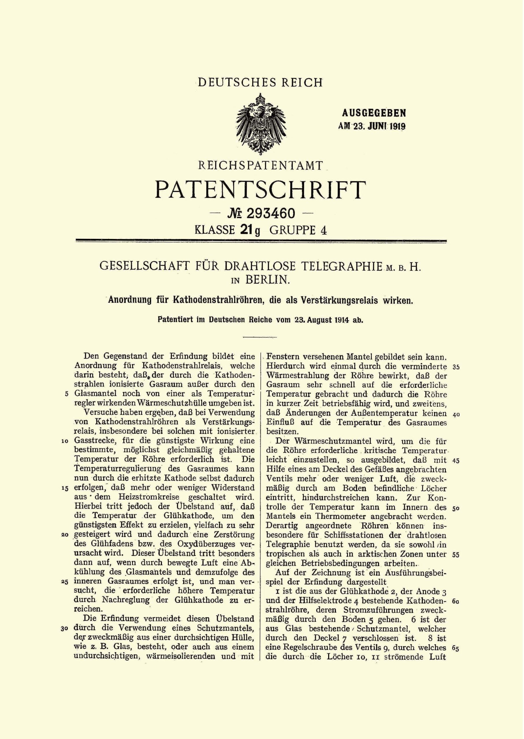

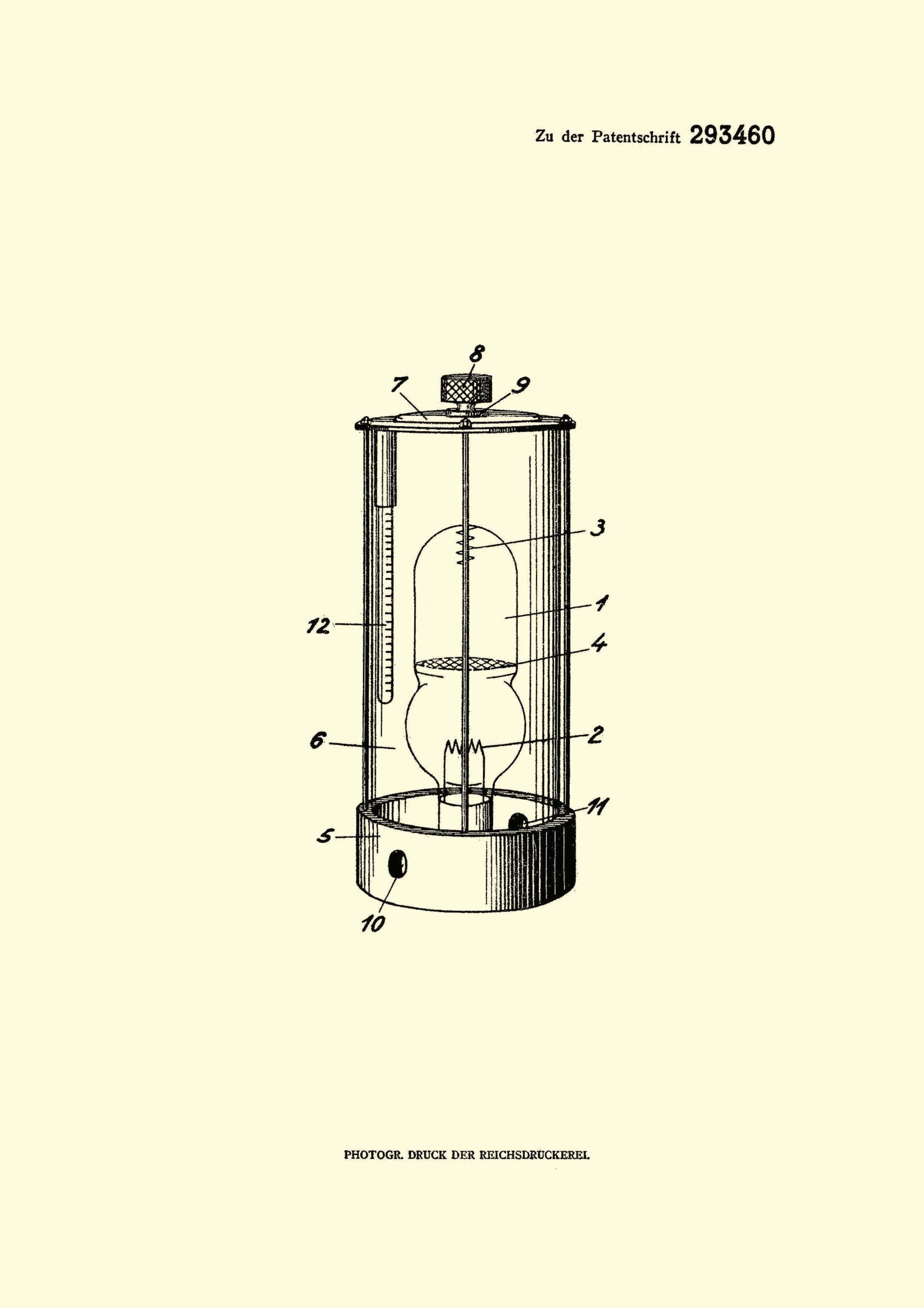
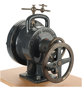
This was the final patent applied for in mid-1914, shown i figs. 18, 19, and 20. It is merely a protective jacket to regulate temperture to improve operating outputs. The last Lieben valve is made in 1922. In 1914, AEG makes a much scaled down version of the LRS, that looks much like the AEG K1. Fig. 21 shows a Gaede molecular pump. Shortly beyond this period, war breaks out between Germany and the allies. This LRS valve was used extensively by Germany and made communication possible in a manner not seen before.
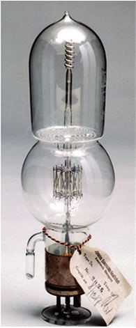
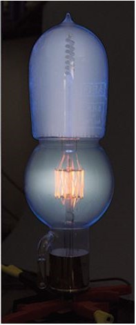
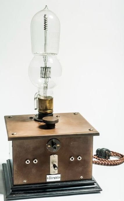
See above the LRS, LRS with the proper voltages applied and the LRS on its control box, all shown in figs. 22, 23, and 24.
Who was first? Many opinions and patent litigation have been determined by judges in different countries so the claims made in this article could be disputed.
Sources:
Price-Hughes, H. A. compiled by, “BTH Reminiscences: Sixty Years of Progress”, 1946. In authors collection.
Briggs, Thomas H., “The Triode That Predated DeForest: Robert Von Lieben and the LRS Relay”, AWA Review Vol. 5, 1990.
Schmidt, H. T., The Life of Robert Von Lieben. Most of the patent documents came from his website and I give full credit to him.
Pichler, Franz, “The Contribution of Robert Van Lieben to the Development of Electronic Amplification”
Blumtritt, Oskar,. “The Lieben Valve: A German Universal Amplifier”.
Tyne, Gerald, “Saga of the Vacuum Tube”. ps.. 235-236.
Scott-Taggert, John, “Thermionic Tubes Used in Radio Telegraphy and Telephony”.. ps. 62-63.