
Forward
This article first appeared in the TCA magazine numbered Vol. 18, No. 2, April, 2016. Since that writing, I have, mostly by accident, found much more information on Hammond and will be expanding the original. First, I will copy the article as it appeared and after I will add the additional newly found facts and where they originated from.
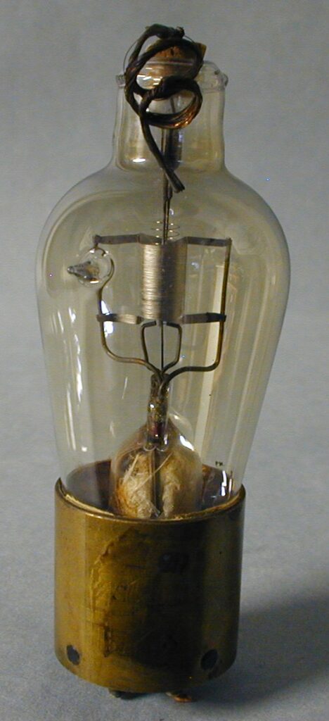
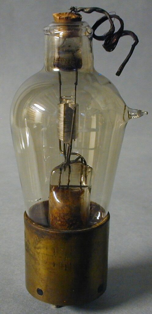
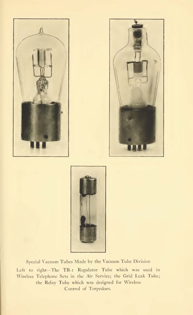
The Hammond relay tube uses a gold tipped 4 pin Shaw base and has the internal structure similar to the VT-12 but the structure is slightly smaller. Only 3 of the bottom pins are used – 2 for the filament and 1 for the plate. The grid exits the top with a multi-strand wire. The filament structure is spiral and fits closely inside the spiral grid. Dumet wire passes through the press. General Electric documents state they developed this special tube for the military and Hammond as early as 1915 [3], but by appearance around the 1917-18 period. [4]. Two views of the Hammond Relay tube are shown in fig.’s 1 and 2.
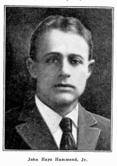
Few collectors are familiar with the early work of John Hays Hammond. Graduated from Yale in 1910, he established the Hammond Radio Research Laboratory in 1911. His company invented a remote controlled dog with a photosensitive homing device in 1912. In 1914, Hammond and Miessner developed remote control devices for his torpedo boat, called Natalia, which used wireless waves sent from a shore station to operate a set of relays, receivers and motors on board. The motors controlled the engine and rudder. The Hammond tube was used in these sets of relays on board the boat and his shore station. These tests were conducted for the possible use by the US Coast Artillery Corps, a division of the US Army, for their use as a costal defense. [1] The Natalia could be loaded with up to 4000 pounds of explosives and could be partially submerged. [2].
Benjamin Franklin Miessner was an expert radio aide for the US Navy and Hammonds right hand man during the development of the torpedo tests. Miessner wrote a book called “Radiodynamics- The Wireless Control of Torpedoes and Other Mechanisms” in 1916 that explained in great detail the steps necessary to control the torpedo boat over long and short distances.[5]
For the purposes of this article, we are interested in the steps leading to the devices that received the transmitted signals from the shore stations. Many were tried including filings coherers- decoherers, Lodge-Muirhead mercury- steel- disc coherers with some success. These were finally scraped in favor of the Hammond vacuum tube detector. The reading of the Miessner book is advised for greater detail.
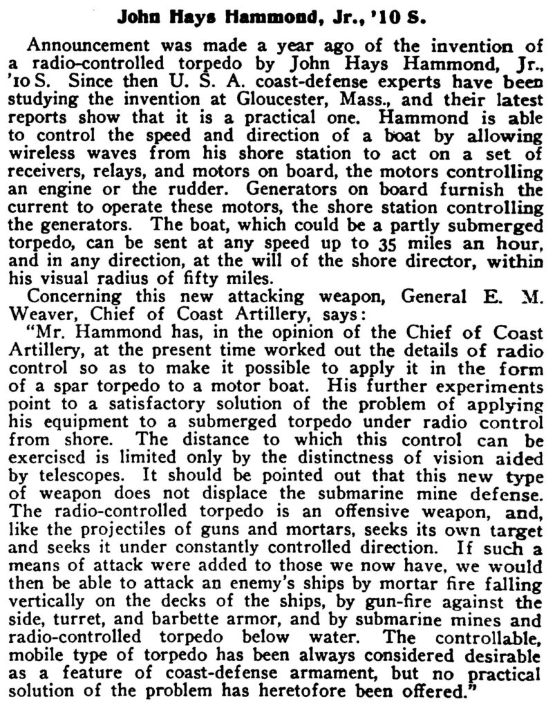
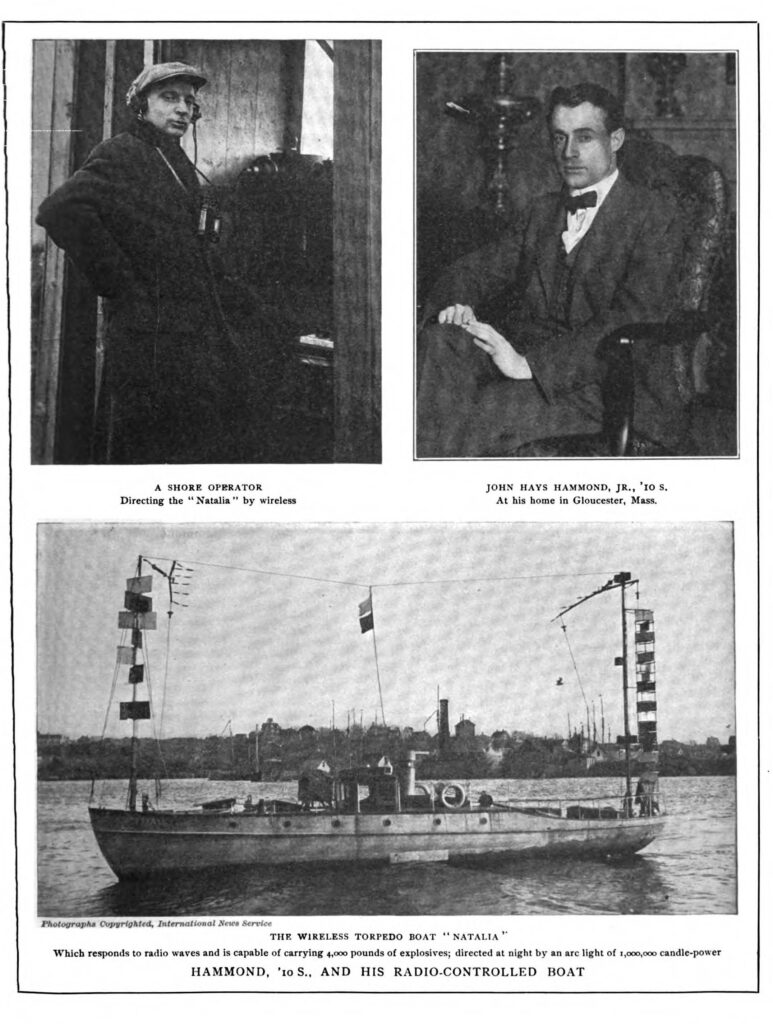
The Hammond boat “Natalia” is shown in fig.4 during one of the tests conducted by the US Army. It’s said to have covered a 120 mile course perfectly under remote control and using the homing device. The boat could be used as a partially submerged torpedo and could be directed from shore up to a fifty mile radius. Hammond was also working on controlling surface and submerged torpedo’s at the time the boat tests were being conducted and for the US Military in the years 1916-18. All the Hammond patents were eventually purchased by the US Military.
Footnote: The Hammond tube resides in the Joe Gruber collection.
Sources:
1. John Hays Hammond Jr. Papers, 1908-1965 (bulk 1912-1953), Manuscript Division, Library of Congress.
2. Yale Alumni Weekly, Jan. 8, 1915
3. White, William, “The Story of Electronics Development at the General Electric Company”, page 19. TCA Special Publication No. 23.
4. General Electric Company, book, “The National in the World War, April 6th, 1917- November 11th, 1918”, pages 246 and 339.
5. Miessner, B.F. “RadioDynamics- The Wireless Control of Torpedoes and Other Mecvhanisms.” 1916.
6. Howeth, Captain L. S. “History of Communications-Electronics in the United States Navy”, 1963, pages 210, 337-339
The remainder of this article is new found material on Hammond. Click on the pictures to view a large version.
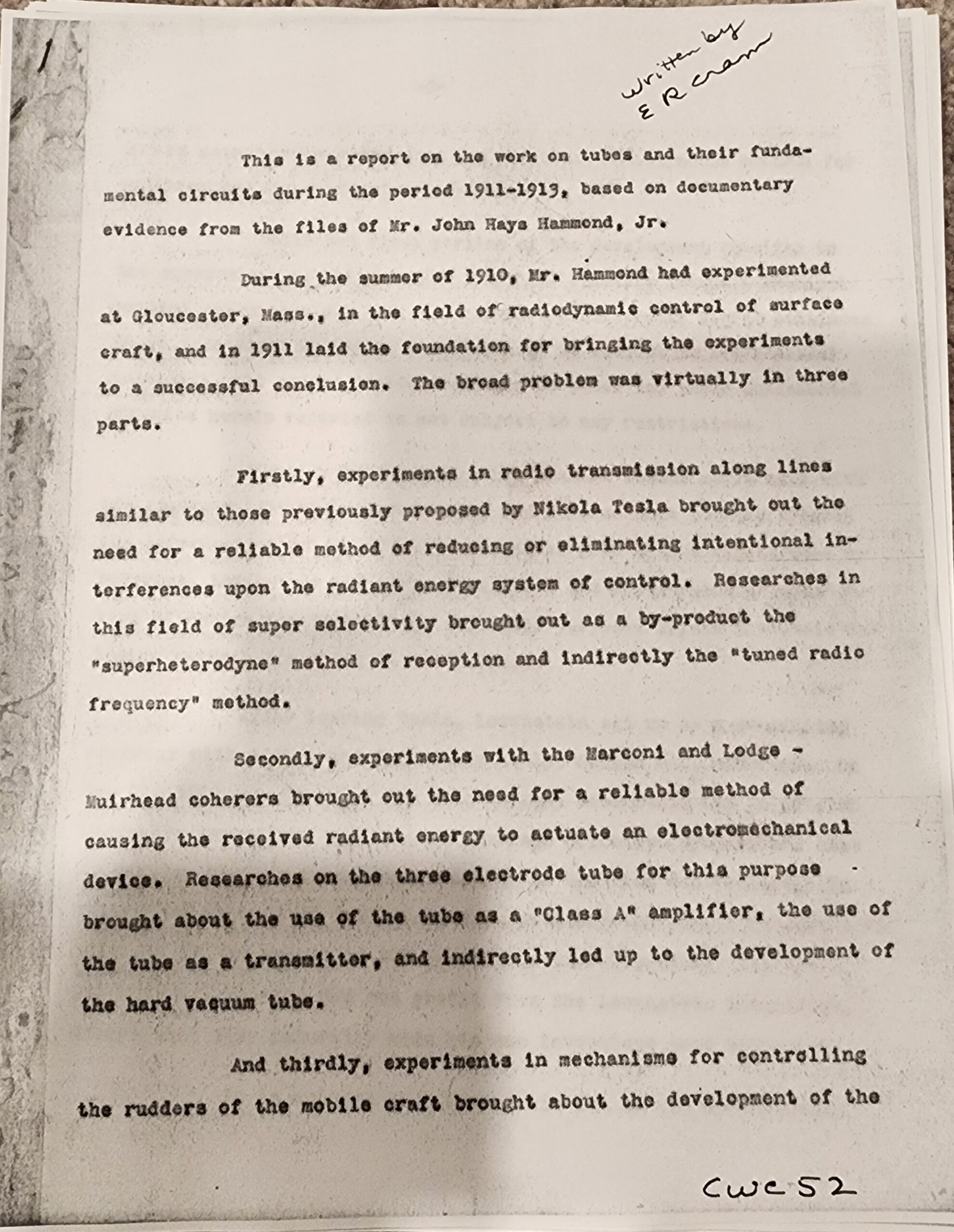
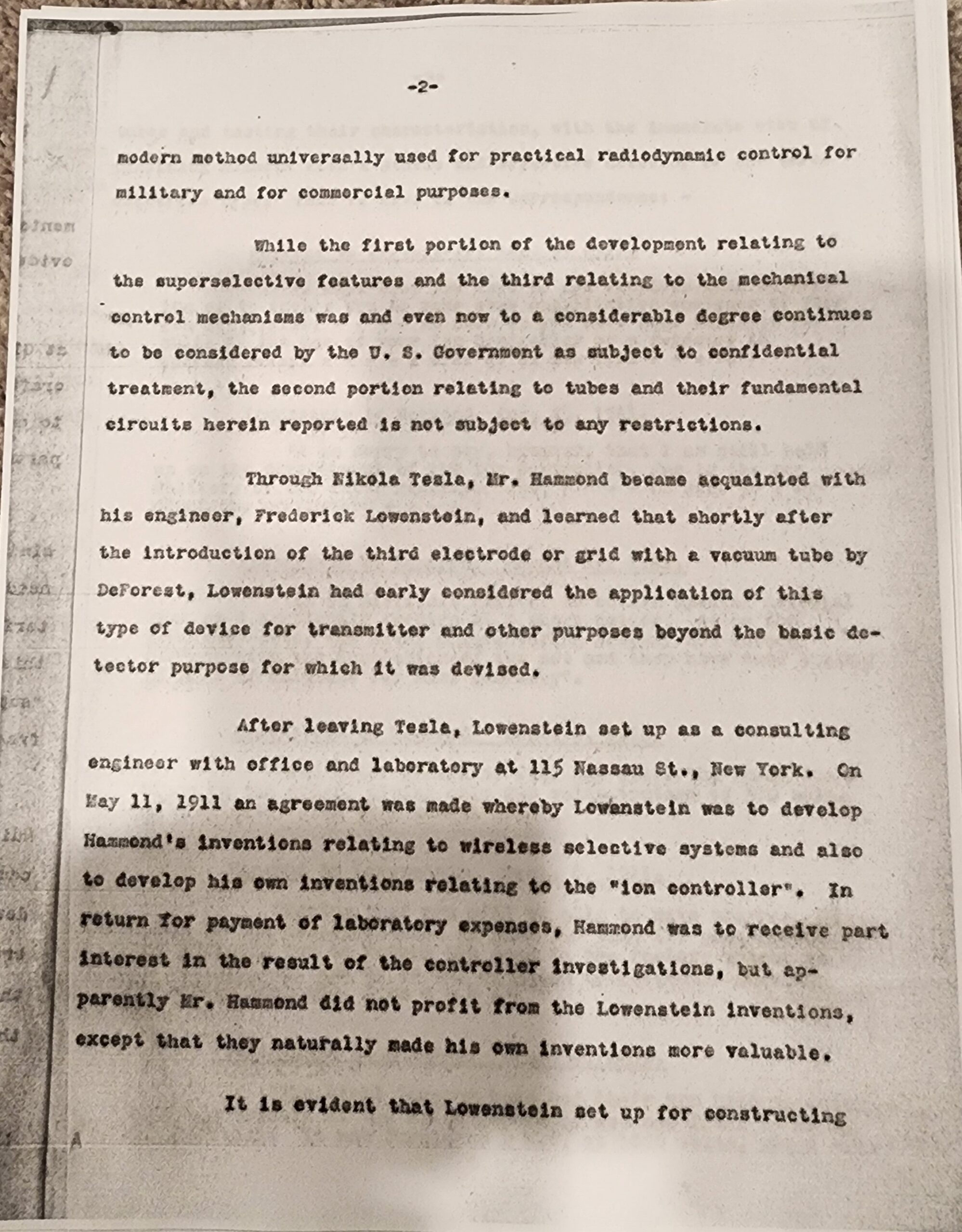
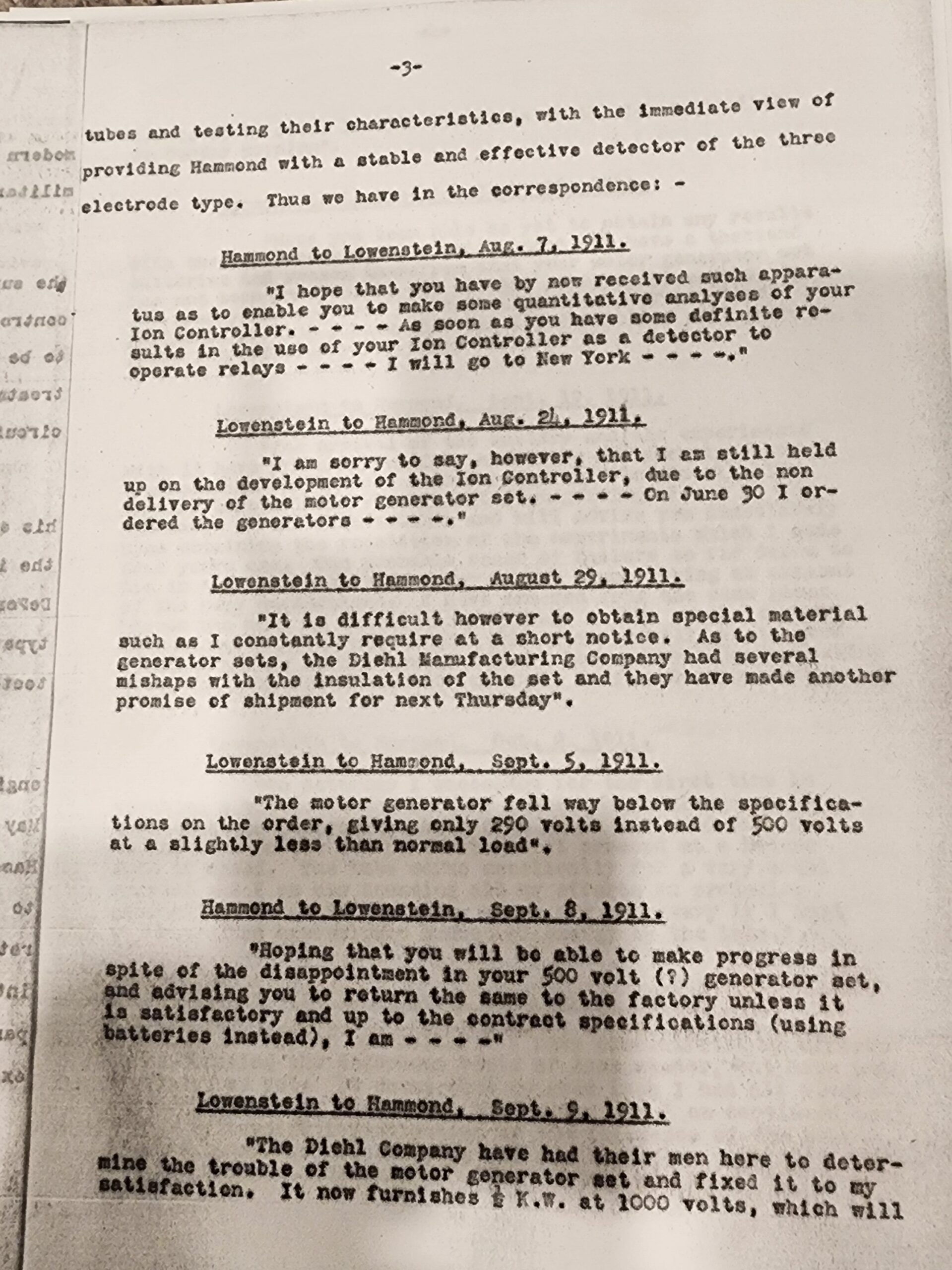
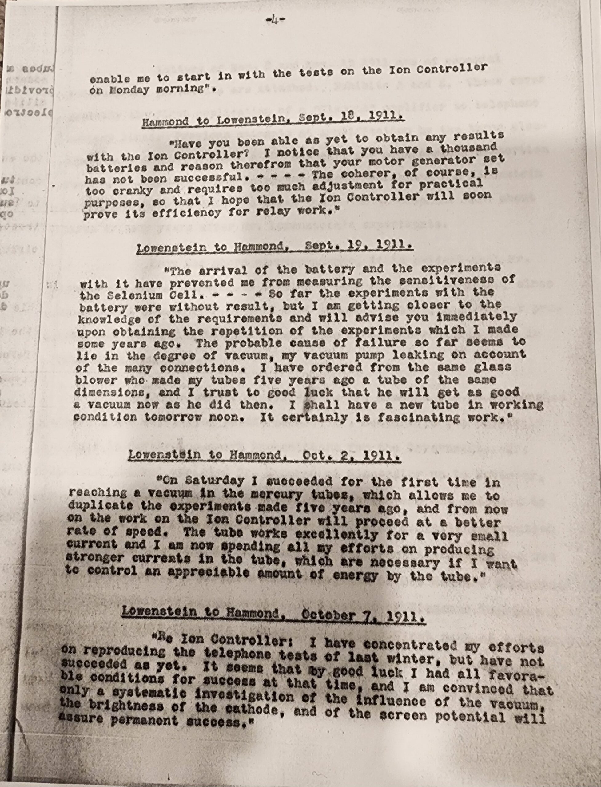
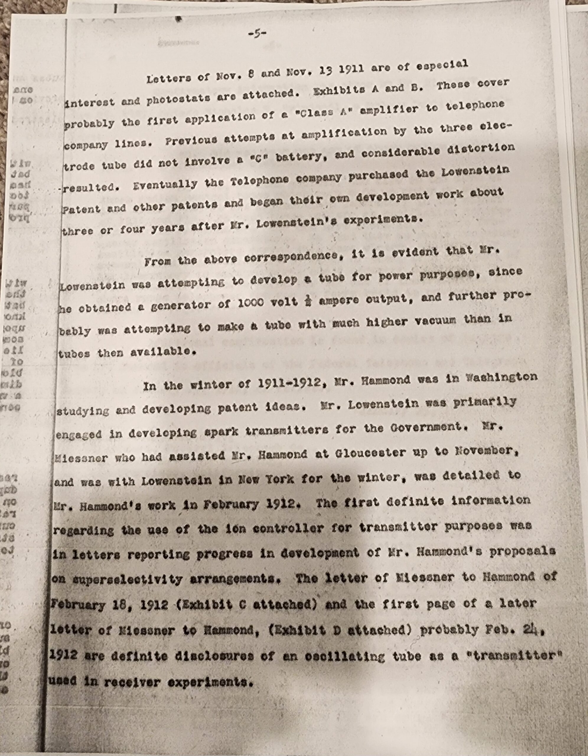
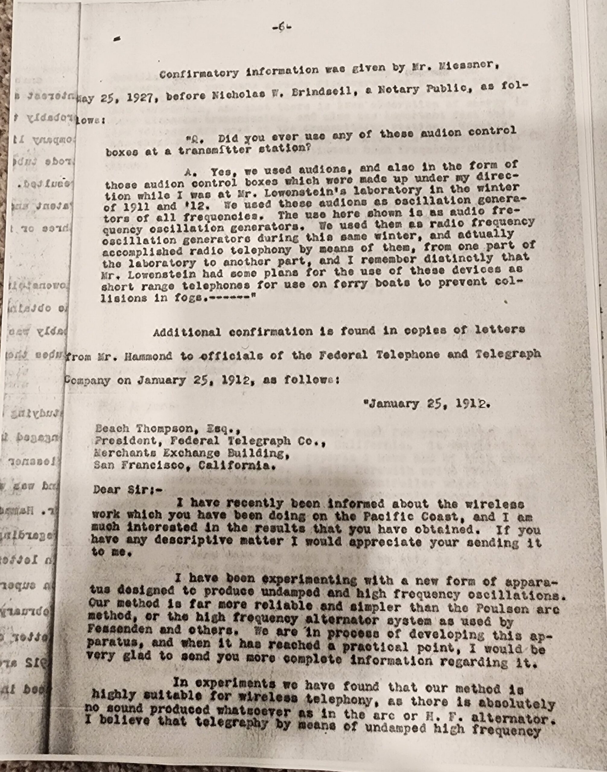
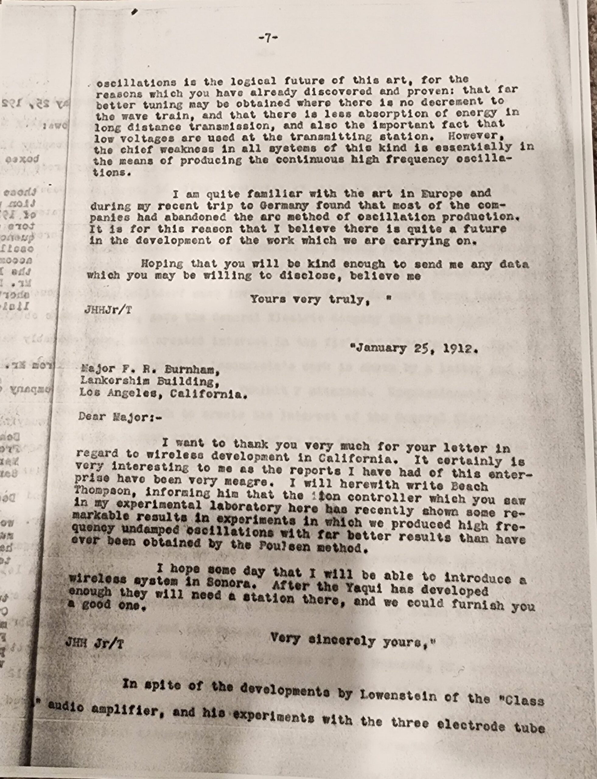
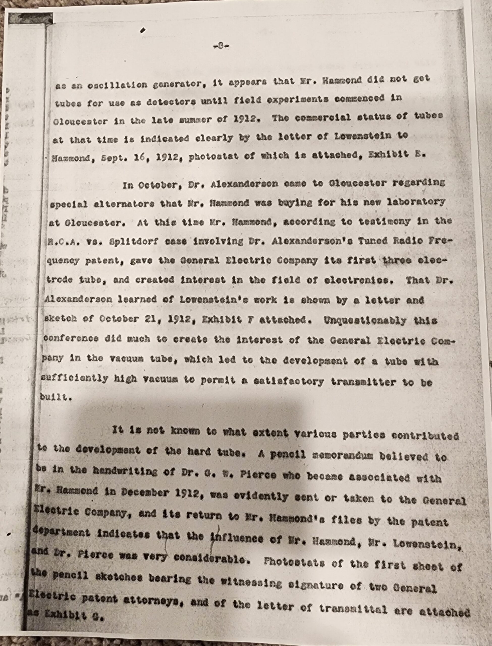
Figures 8-16 are pictures of the work of John Hammond in the years 1911-1913 from the George Clark “Radioanna” collection in the Smithsonian. These papers show the early ground work of Hammond and laid the foundation for his many fields of interest including his US Navy torpedo work. The pictures were taken by Robert Gillispie in the year 2022 I believe. [7]
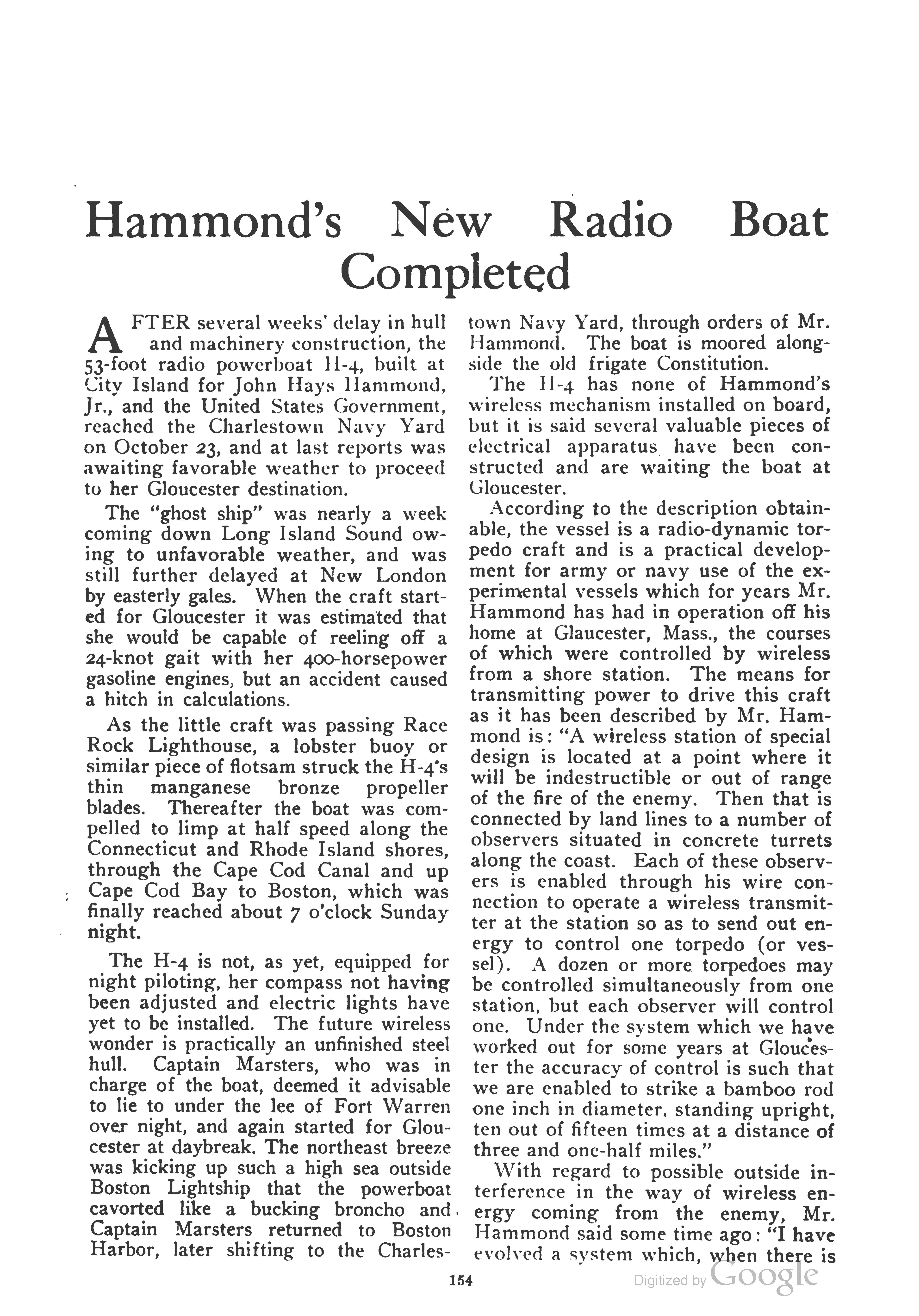
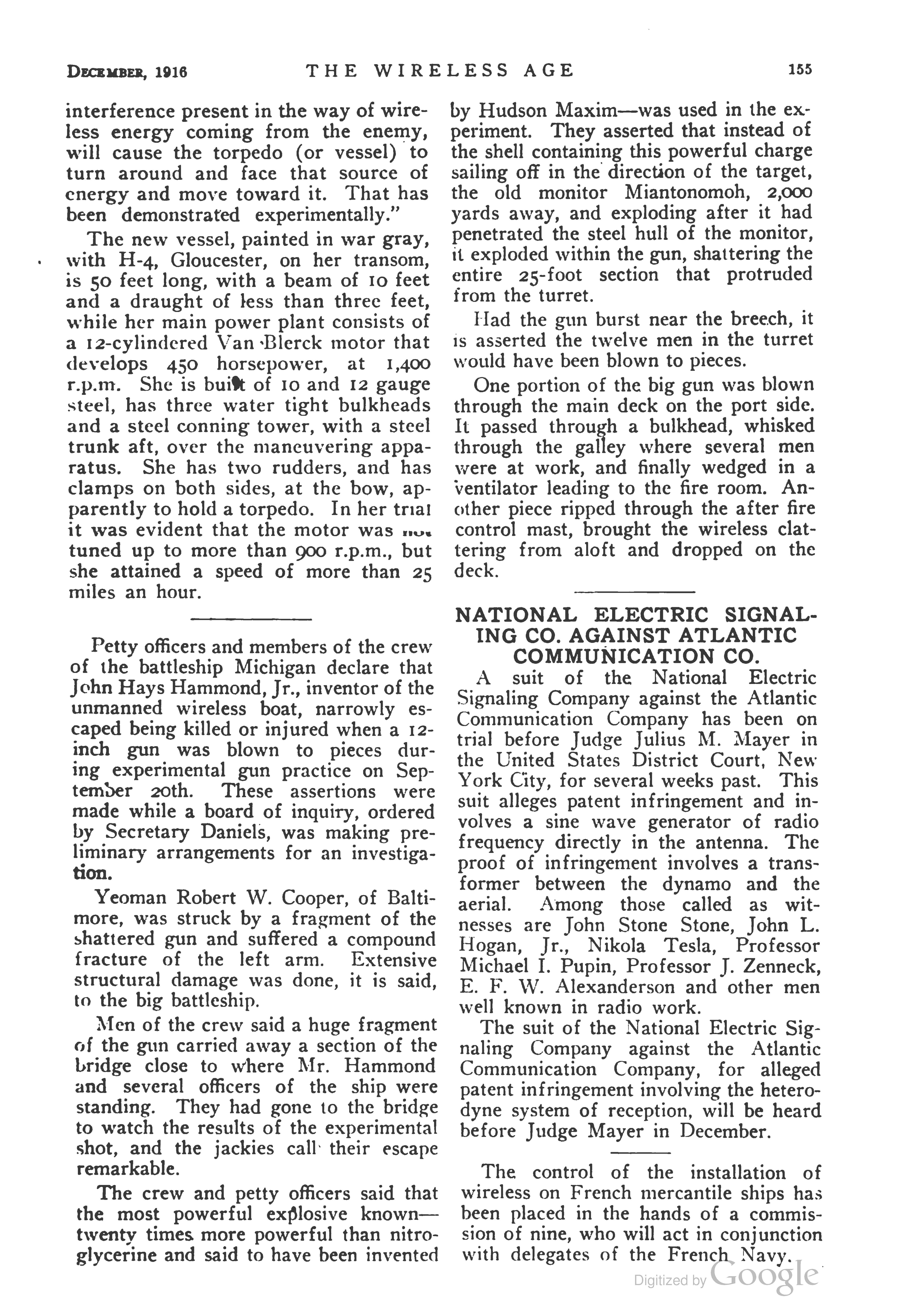
Figures 17 &18 is a contemporary article on the completion of Hammond’s radio controlled boat that appeared in the Dec., 1916 issue of “The Wireless Age”. [8]
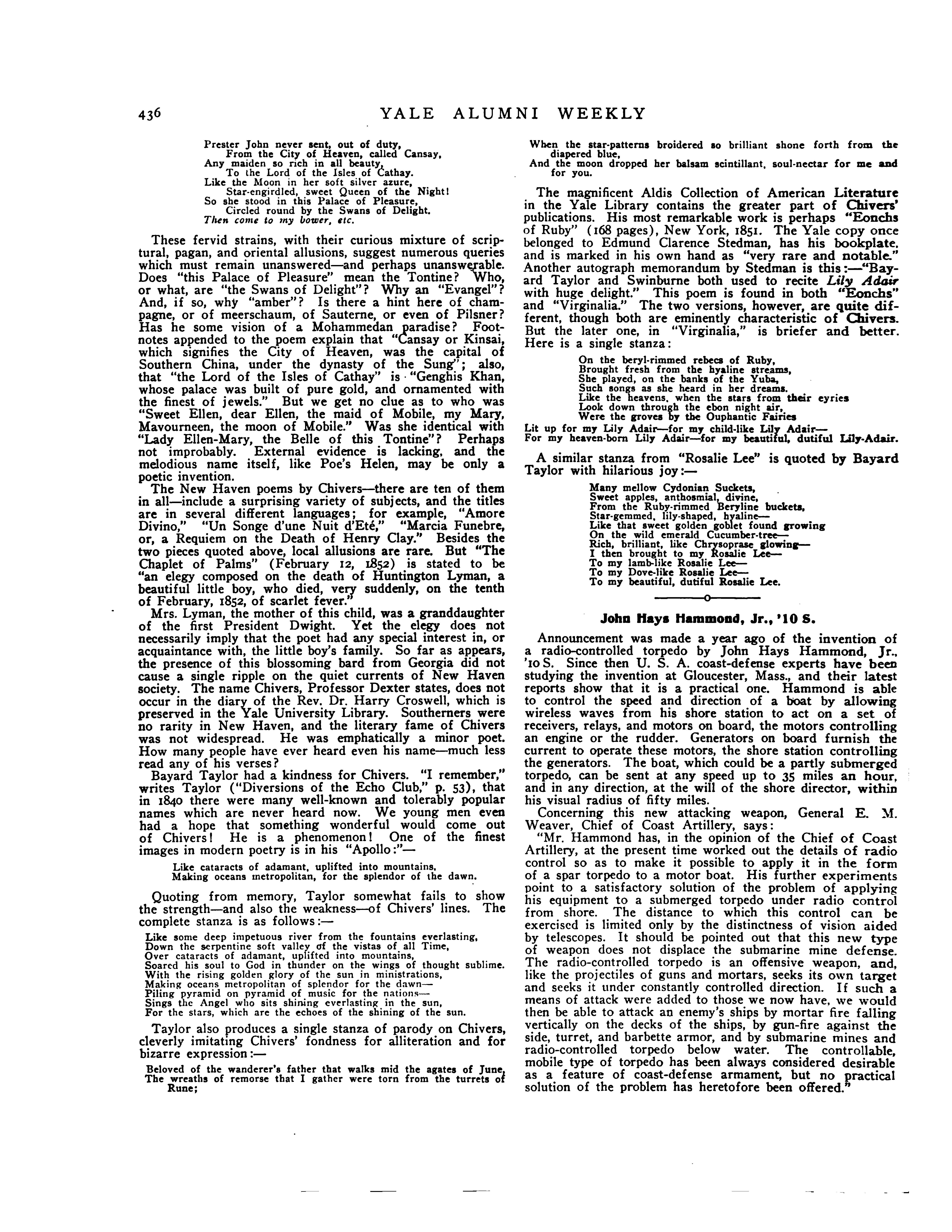
Fig. 19. Yale University mentioned Hammond in their alumni paper around 1915. He graduated in 1910.
Fig. 20 is the cover page of the IRE article on Hammond. Click here for the entire article: JH_All.pdf
Figure 21 is the cover page of a US Navy report on the development of torpedoes. Click here for the entire article: USN_A.pdf
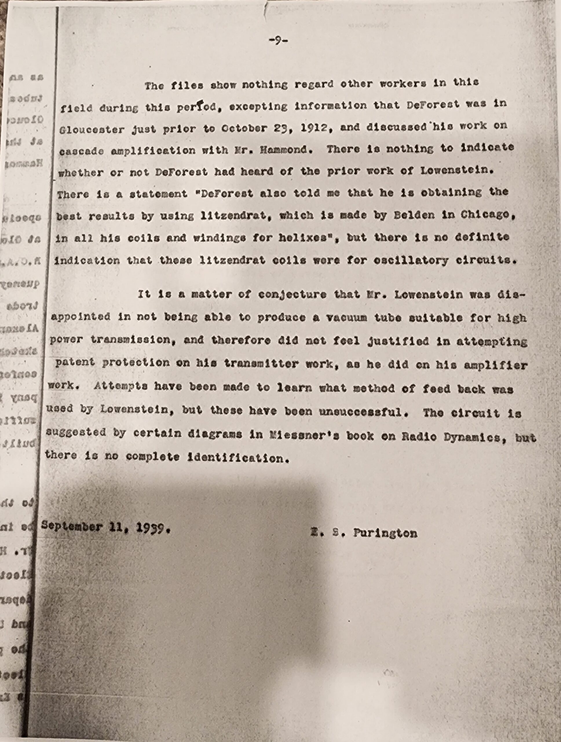
Figure 22 is the cover page of a IRE LLoyd Espenshied critique of Hammond’s work on torpedoes. Click here for the entire article: DE_All.pdf
Sources:
7. Pictures of the Hammond papers taken at the Smithsonian provided by Robert Gillespie.
8. “The Wireless Age”, Dec., 1916, pages 154-155.
9. Yale University alumni paper, 1915.
10. Proceedings of the IRE, Revised manuscript on June, 5th, 1957.
11. US Navy 1988 report on the development of torpedoes.
12. Cover page of an IRE critique report of Hammond’s work on torpedoes.by LLoyd Espenschied, Dec., 2nd, 1957.
13. Further reading could be sought in a book by B. F. Miessner called “Radiodynamics”, 1916, IREE, expert aide to the US Navy.
Leave a Reply