
By Joe Gruber
Vacuum tube collectors may ask- What is the Eaton tube anyhow? This author will attempt to answer that question along with addressing the description of each tube in that collection. Esteemed tube collectors Jerry Vanicek and Lauren Peckham laid a foundation as to the identity of each tube, keeping in mind that the original describers may have made mistakes. Jerry and Lauren did not always see eye to eye on this subject. To Lauren’s defense, he borrowed the Eaton collection from the AWA archives and may not have had all that was needed to make a good guess as to the ID of each tube. Jerry, on the other hand, had original pictures from the Tyne collection to study in detail to make his guess. His study may be flawed as well as this author is not certain that Jerry used the important negative pictures to ID the tubes. The negative pictures, as opposed to the positives, give a much better view of the internal structures and paper tag writings. I will concentrate on the US Navy types of various that was assembled at the Bureau of Steam Engineering, in their Navel Yard in Washington, DC., that became the Eaton Tube collection. I will give it my best to ID them using all the best methods possible.
As the US involvement in WW1 approached, all patent litigation ceased so companies large and small could submit their vacuum tubes to the military to be tested and if found to be worthy, the makers would be contacted to start production. Hundreds, perhaps thousands were shipped to all branches of the military. Once the US had committed to join the battle, German tubes of all sorts were found as well, from British and French forces as well, and these were added to mix to be studied.
After WW1 ended and sometime in early 1919, the Navel Yard in Washington, DC probably had hundreds of submitted and captured vacuum tubes lying about. It can be speculated, and while not being certain, that Lieutenant William Eaton, officer in charge of the radio department at the Washington, DC Navel Yard, was ordered to assemble the radio receiving tubes of various types the Navy had in their possession, probably by Navy Commander Paul G. Watson. Watson is responsible for the Eaton collection to be in the collection of Tyne to begin with. This is made clear when looking at the collection of pictures in the Tyne collection and seeing the name of Paul G. Watson in red on them. Eaton went on to have a fairly- long and distinguished career with the “Wireless Specialty Apparatus Company.” While Eaton probably had much to say as to what specific tubes were to be added to the collection, it was left up to his expert radio aide Lawrence Horle to assemble the tubes, have a cabinet made to hold them, secure the tubes to that cabinet, have pictures taken and submit them to Eaton for final approval. This was done and it became the Eaton Navy collection. This author has learned that most of those involved were given a set of positive pictures along with the descriptions and perhaps a catalogue of same. Ted Duvall, an electrician in the US Navy was assigned the task to make the tube cabinet. Years later, Duvall gave the catalogue that was made to AWA founder Bruse Kelley for his museum.
George Clark must be mentioned here for accuracy. George worked for the US Navy during WW1 with the title “Chief Radio Aide.” In this capacity, he devised the numbering system for the entire US Navy and a great many other facets of radio. This evolved into the early tube period, and while he was not a tube researcher or historian, he did develop a passion for the collecting of pertinent documents and examples of radio. He also figured into development of museums and solicited donations from the military and other individuals and companies. During this time, he became friends with all the big names in early radio and vacuum tube development like De Forest, Haraden Pratt, Lt. William Eaton, Ben Meissner, and many others. His friendship with William Eaton and while working for the US Navy led to his use of the Eaton collection in his traveling shows while working for Marconi and RCA around 1933. There is the connection between Clark and the Eaton collection. George, with his collecting examples of tubes, radios, pamphlets, catalogs was called on frequently to testify in patent litigation cases accoss the country. there a number of these cases typed up by Clark in preparation for them in this authors collection.
As a sidelight, this author recently spoke with Jim & Felicia Kreuzer, in charge of the AWA library, and found the Eaton material is in the library but they are unsure if it is complete with the pictures, description, etc. If the AWA does not have them, this author will provide them along with all supporting documents, and this would mean that whoever owns the Vanicek paper collection and I may have the only surviving Eaton pictures and documents known. They will be preserved on vacuumtubearchive.com
Click on the Eaton US Navy documents below to see a larger view.
More below
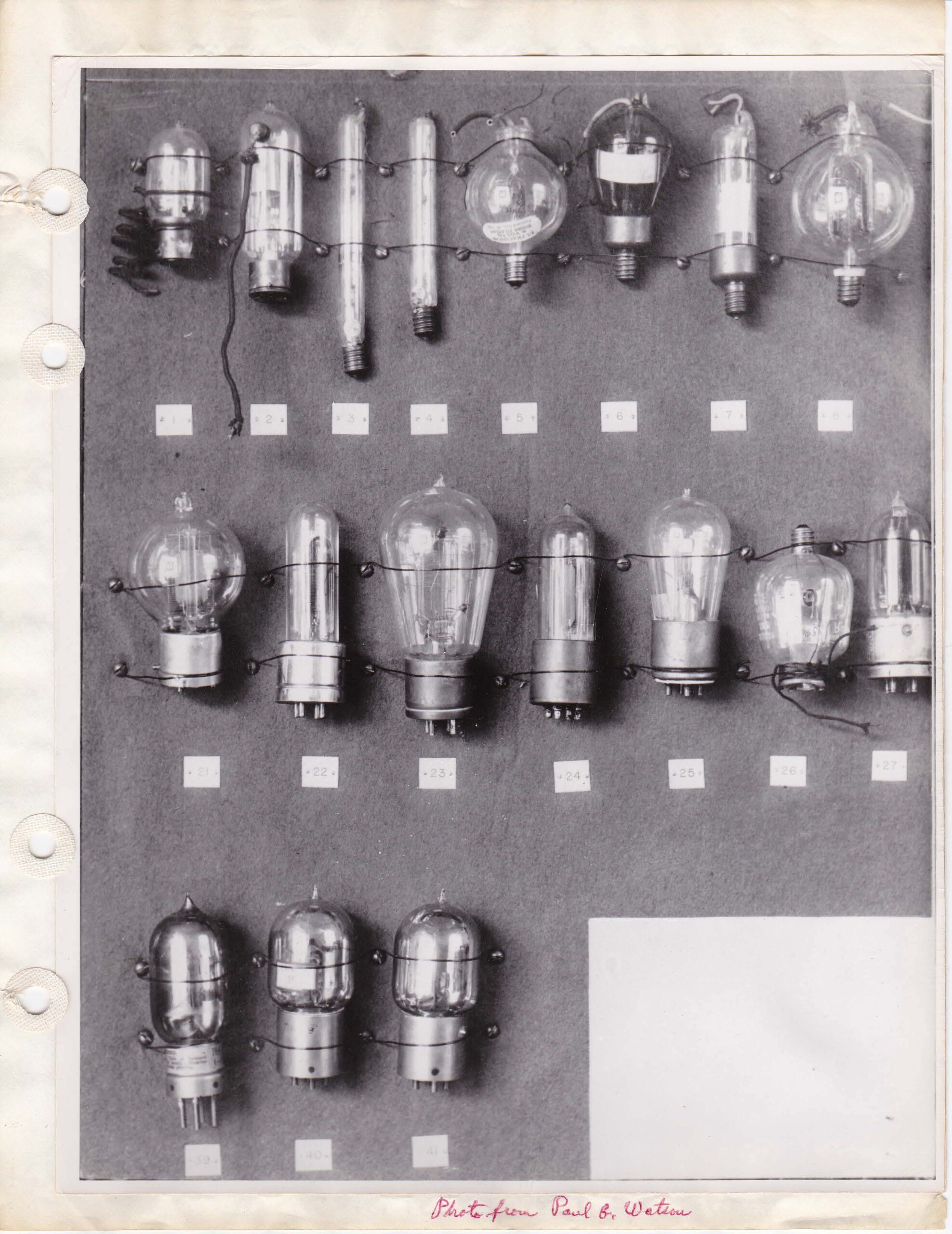

Below find the explanation of the pictures above.
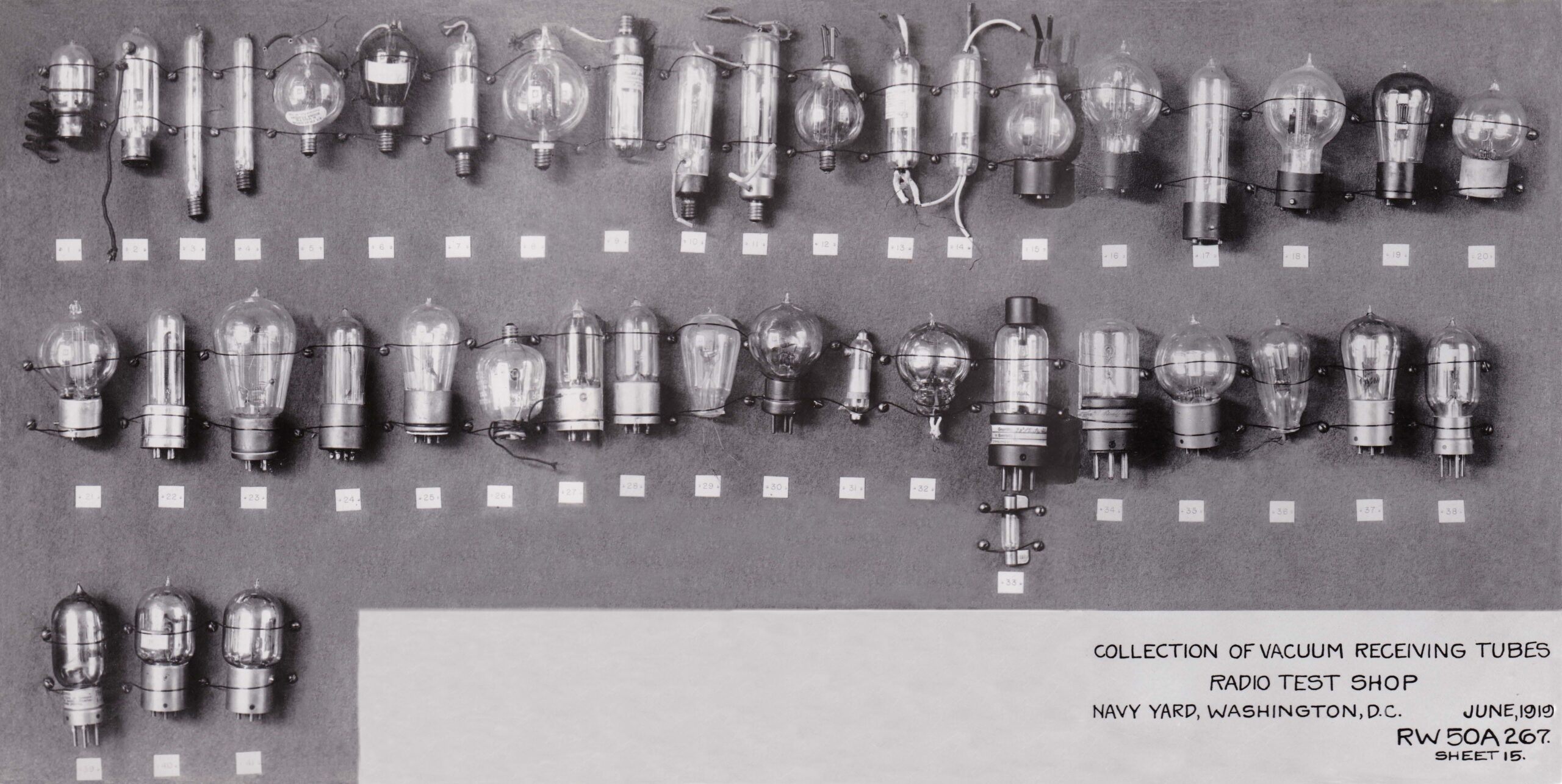
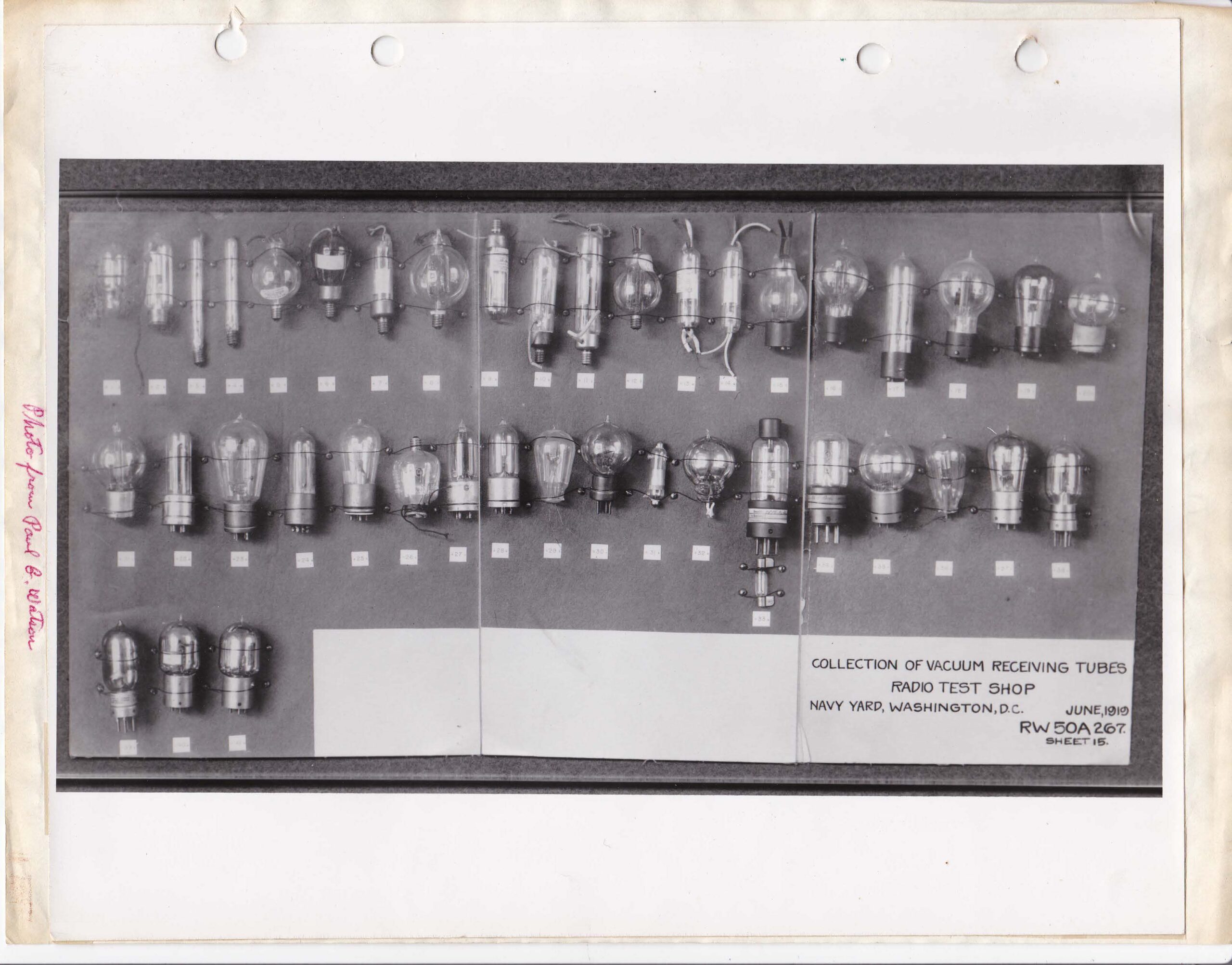
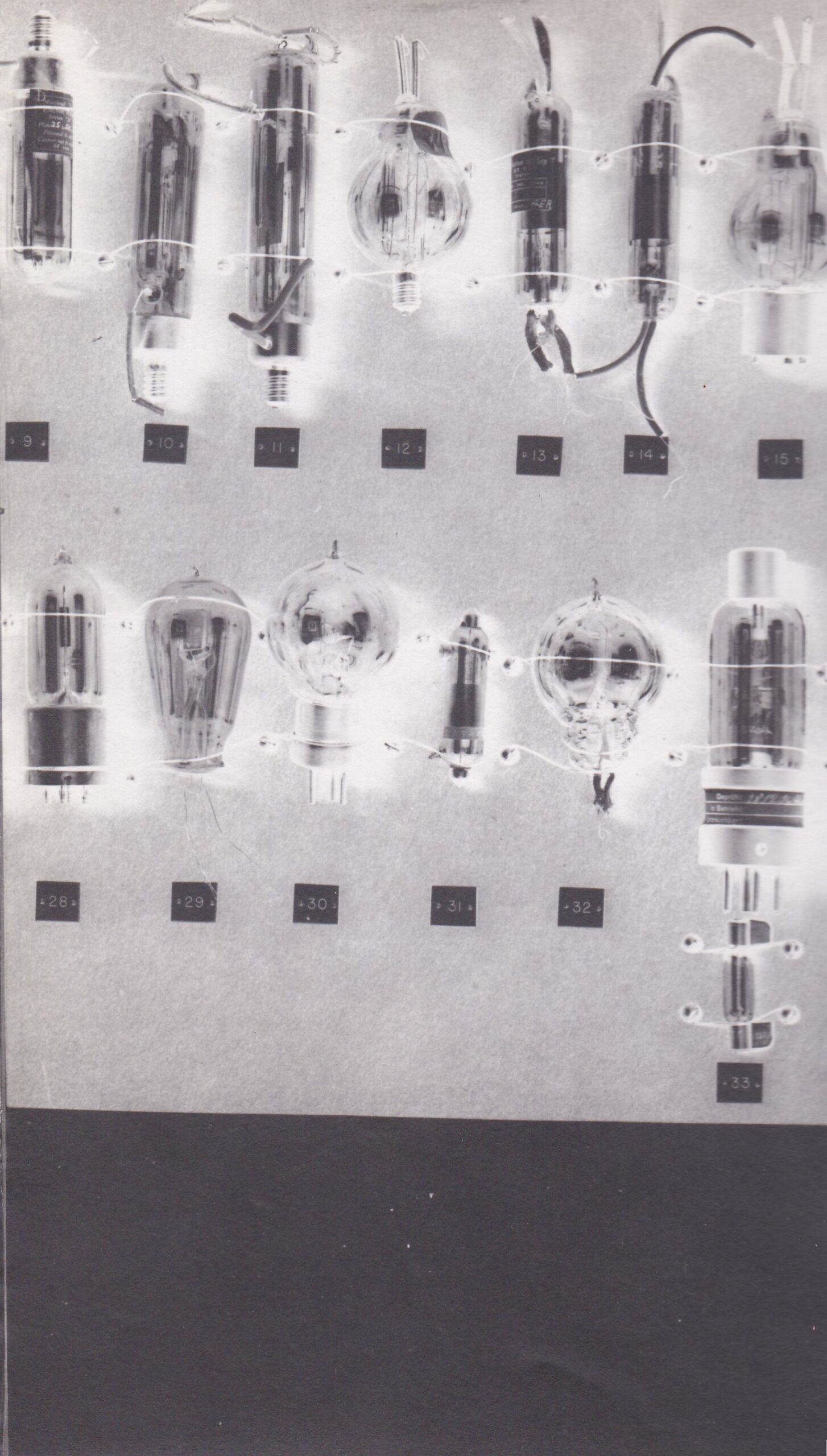
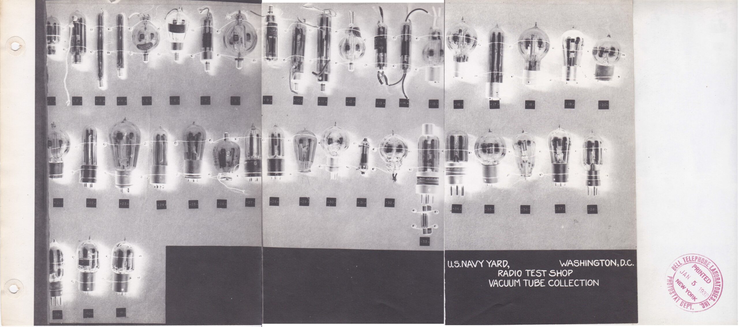
Fig. 1 This is the first picture this author attempted to correct. 3 separate pictures were taken originally of the collection so I combined them into 1. As can be seen, much work was going to be needed to remove the 2 lines between the 3 pictures, add what was missing when doing so and evening out the gray colored backround.
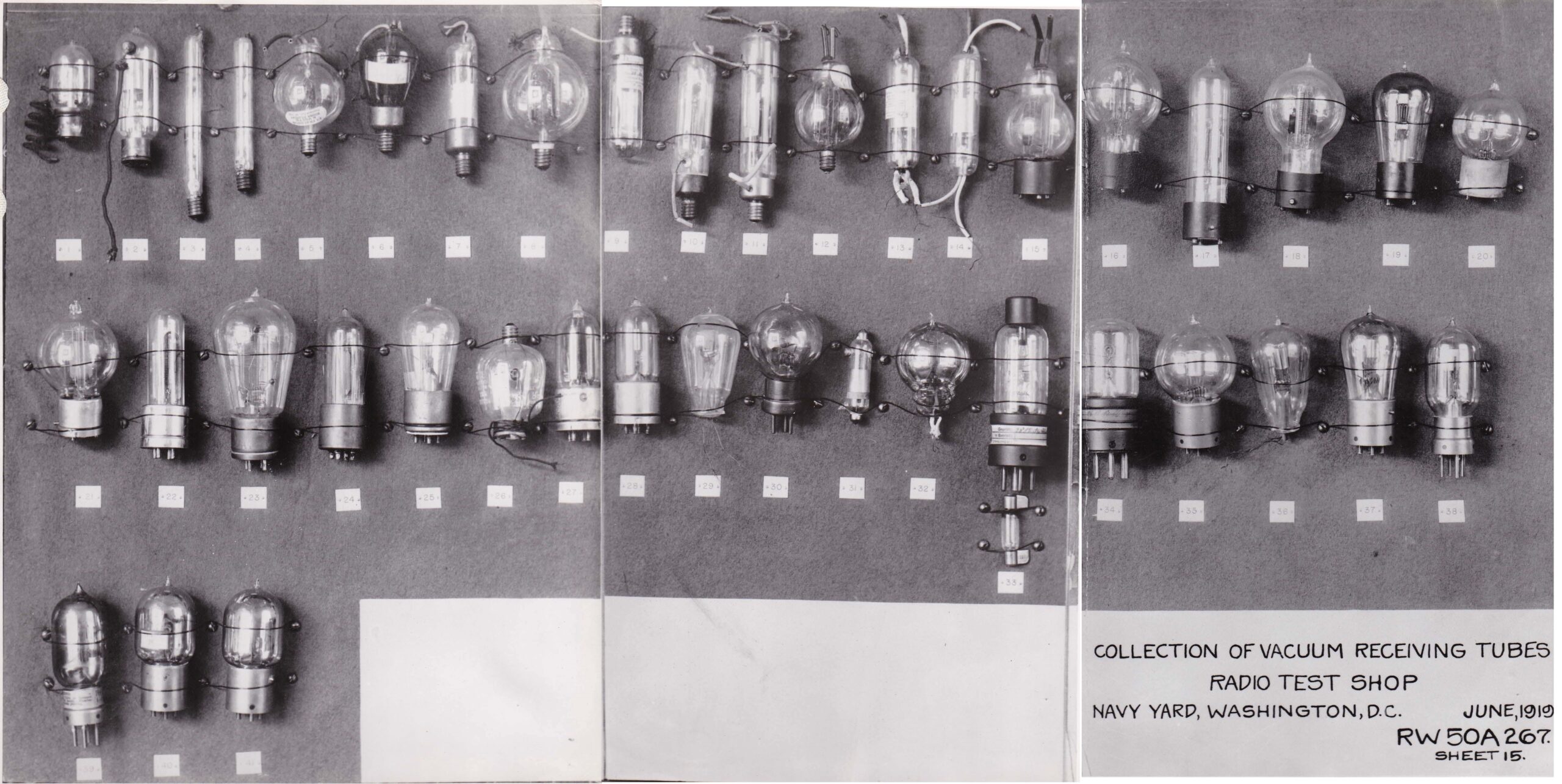
Fig. 2 This is the fully corrected picture of the Eaton collection this author has made. Helps just a bit in ID’ing the tubes.
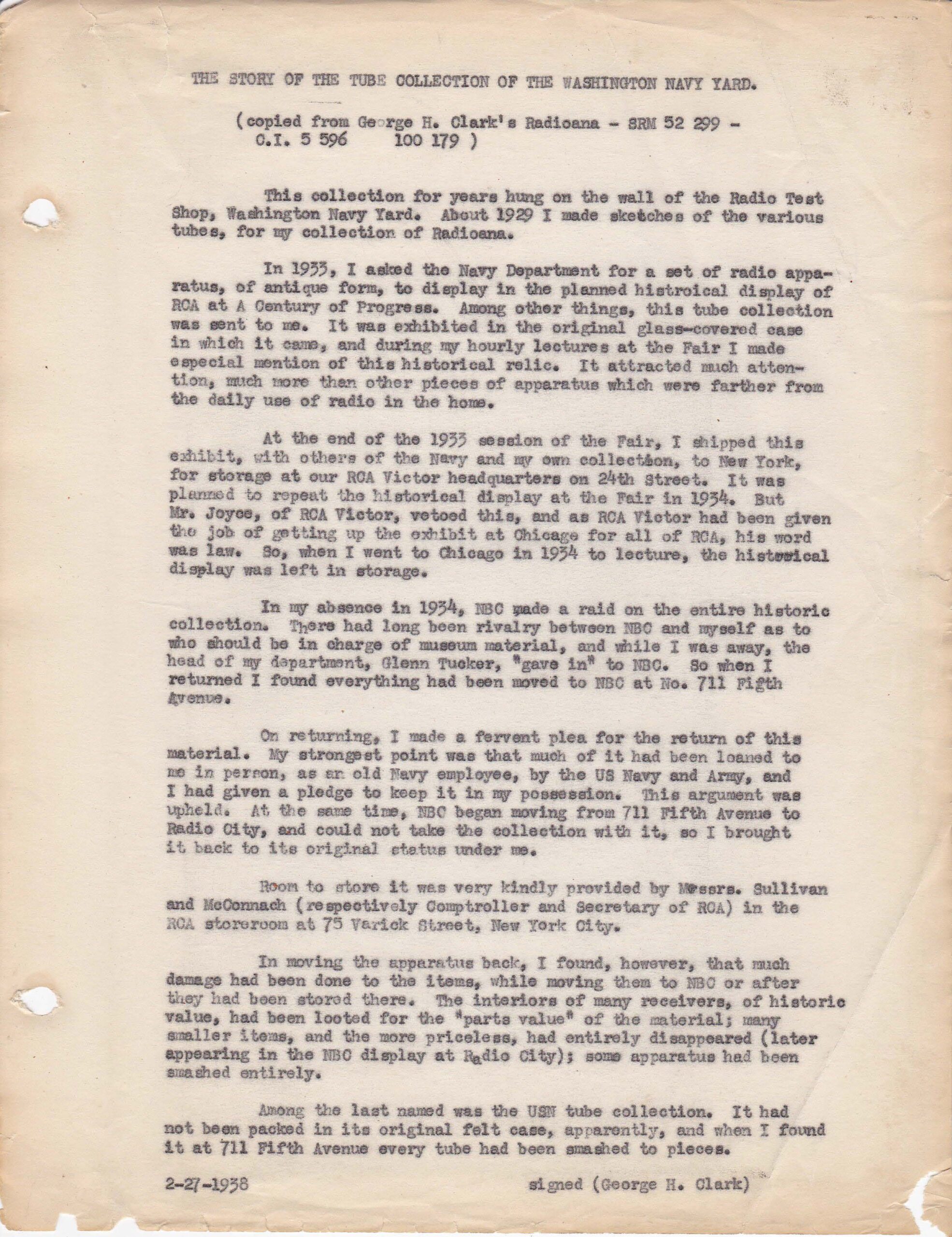
Fig. 3 Tyne’s original type written copy of George Clark letter explaining the history behind his use of the Eaton collection and it’s demise from Clark’s “Radioanna” collection.
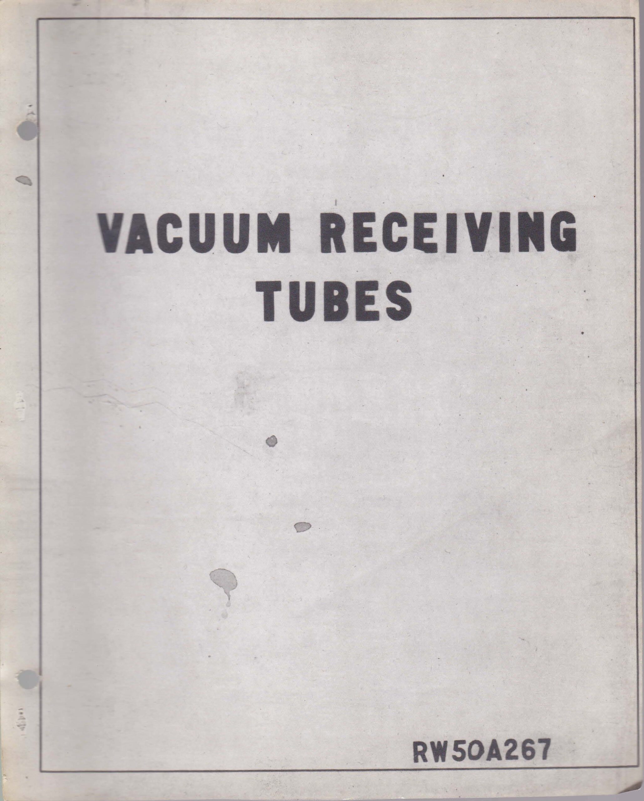
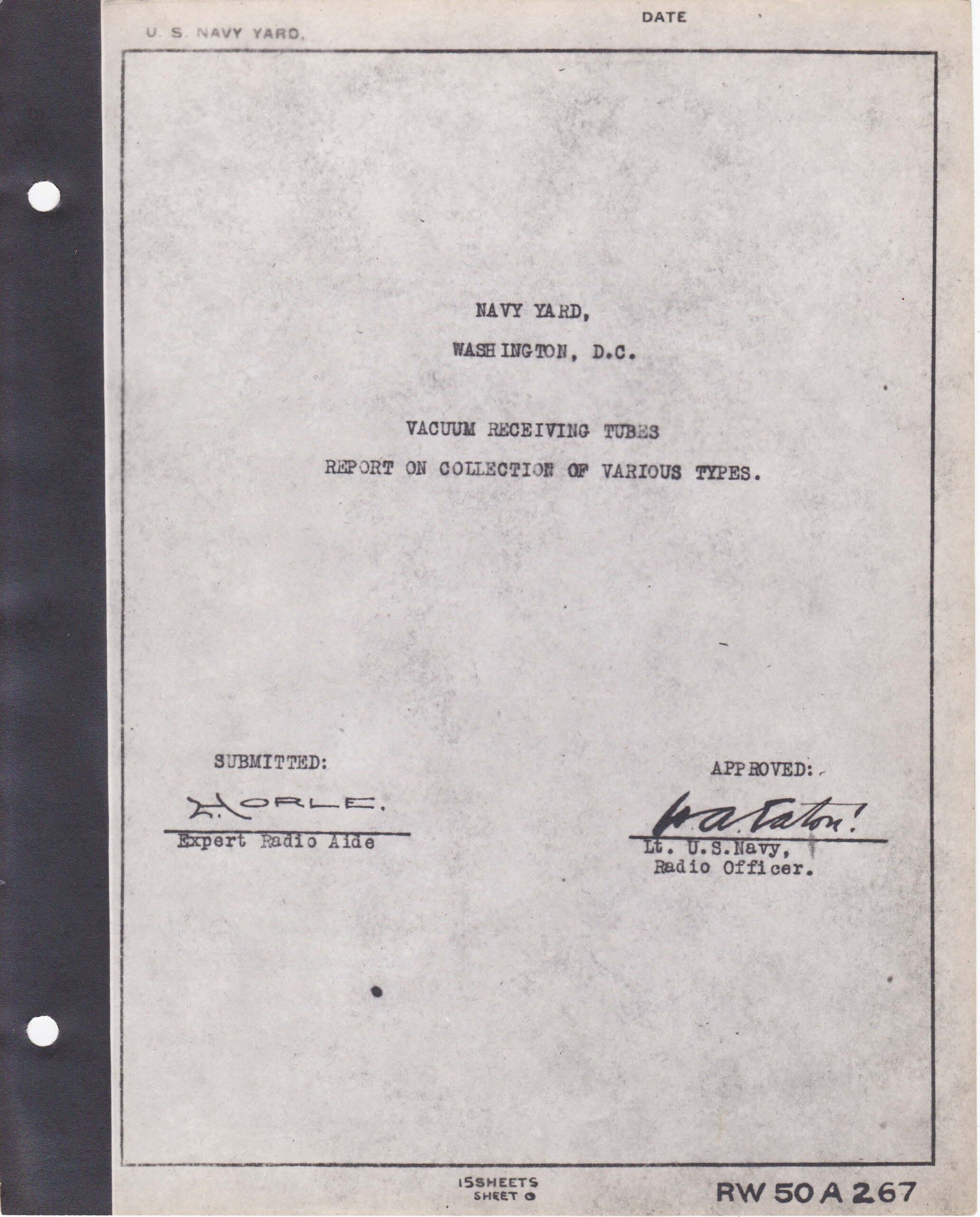
Figs. 4 & 5 Cover page and authorization page with Eaton and his aide Lawrence Horle signatures. Many of these pages were numbered RW50A267, the number probably given by Horle. There were others involved, perhaps Clark himself, but we may not know for certain? Ted Duvall was one we do know, as he, with another helper, made the wooden cabinet and probably mounted the tubes inside. He was given examples of the pictures and apprantly given a catalog as well. Ted donated them to Bruce Kelley for his AWA Museum. Ted later became an early ARRL official and the most active early amateur historian. He also worked for Nesco and was involved in the 1915 radio transmissions from Arlington, Virginia to San Franscisco, Ca and to the Effiel Tower in Paris. Another tie to the Eaton tube collection. More about Ted later.
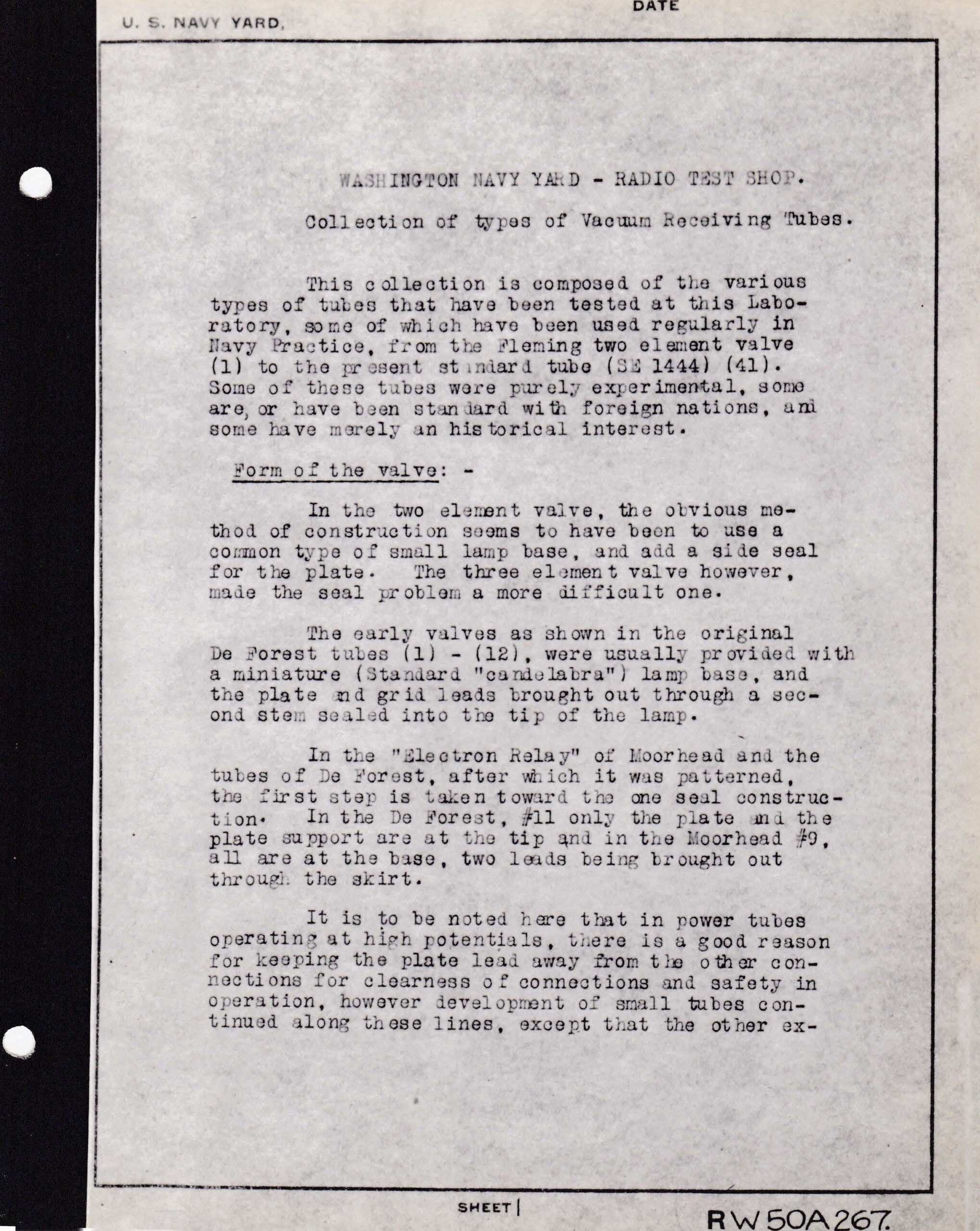
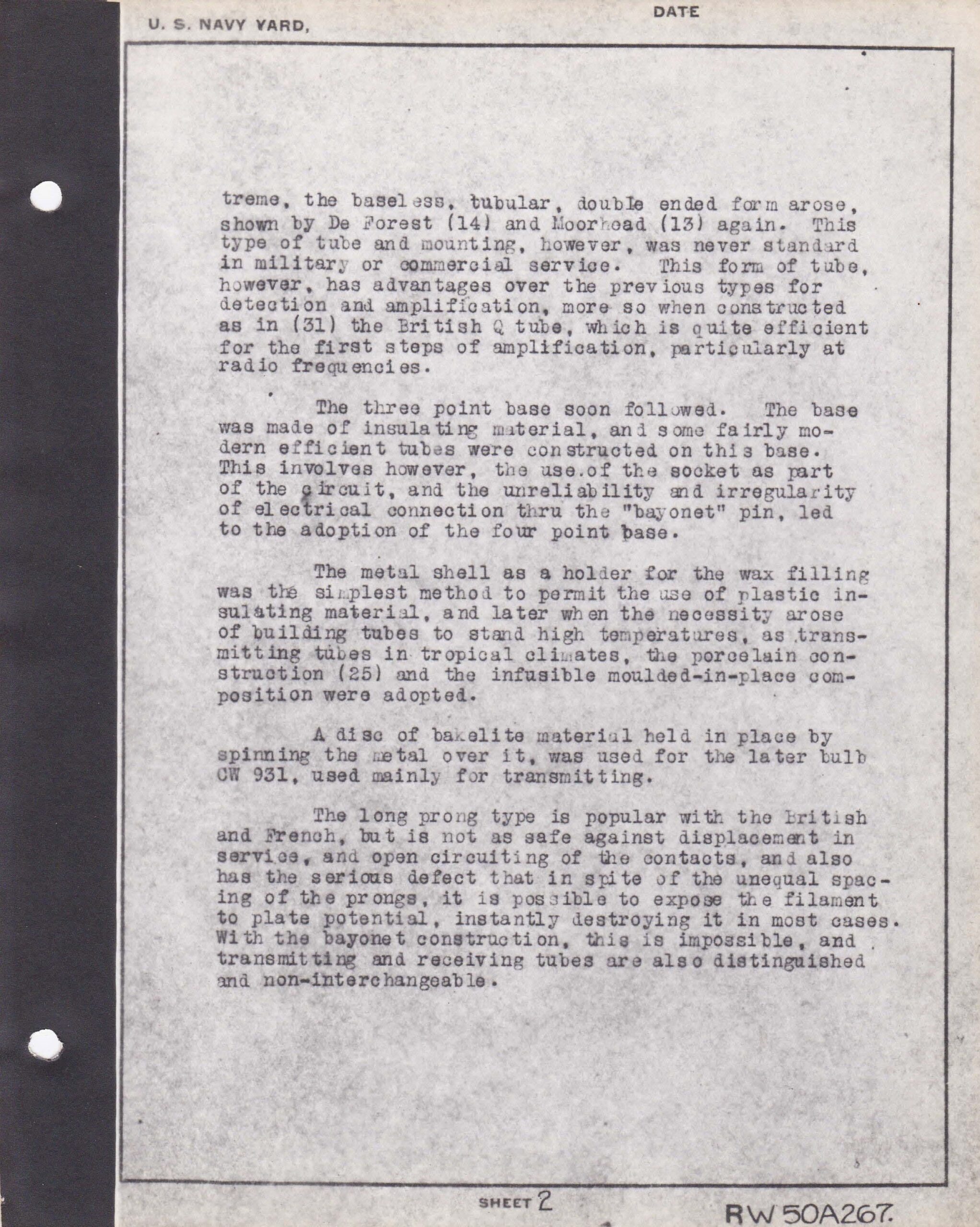
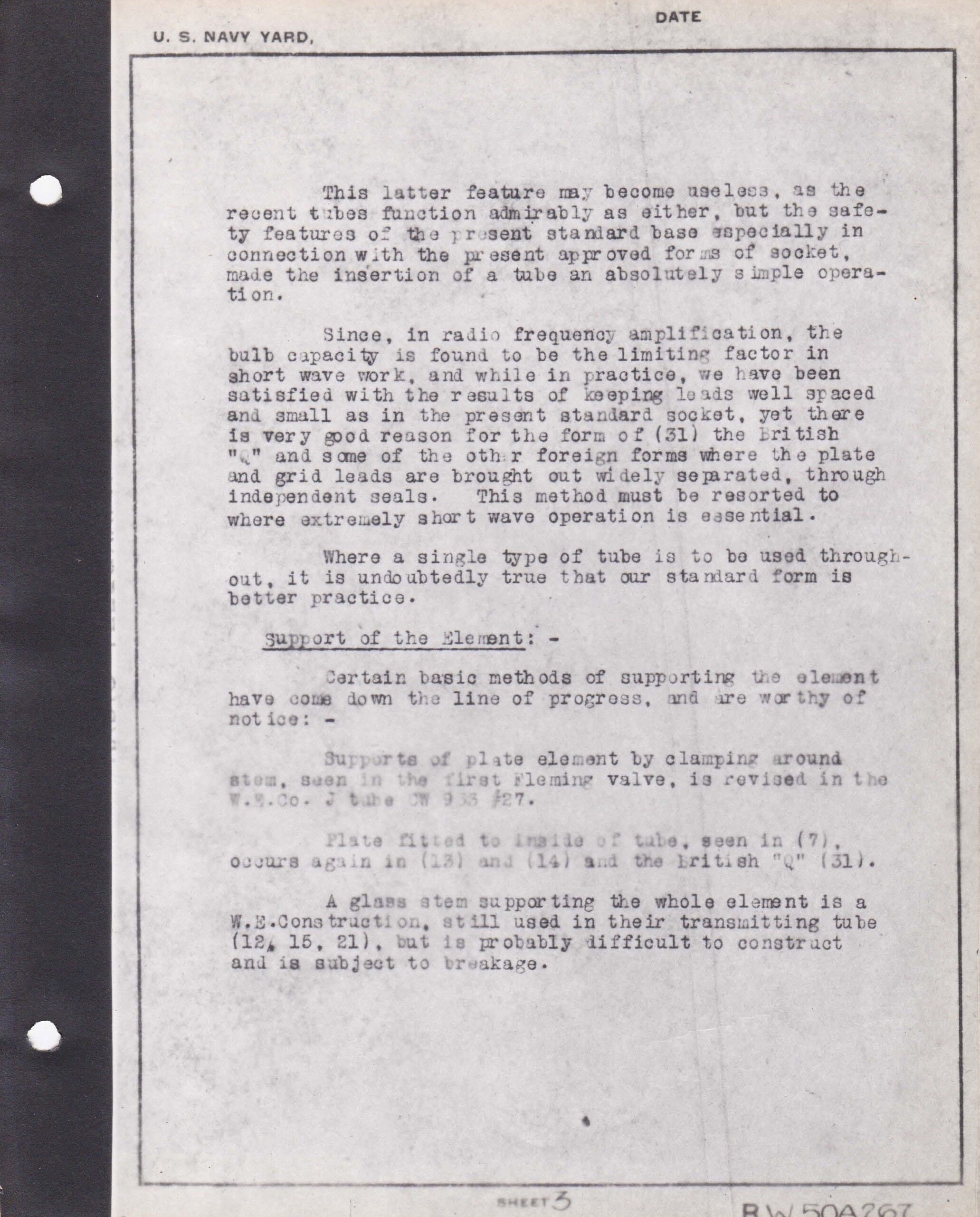
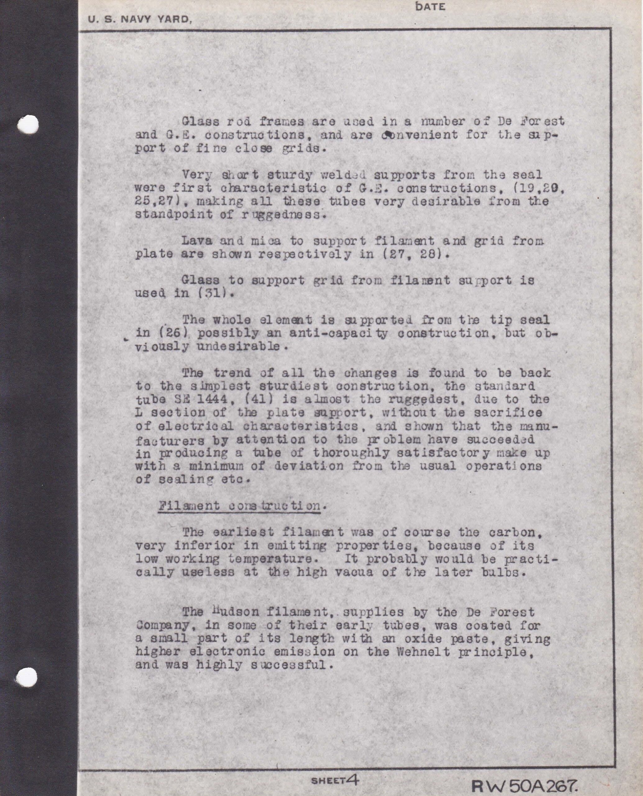
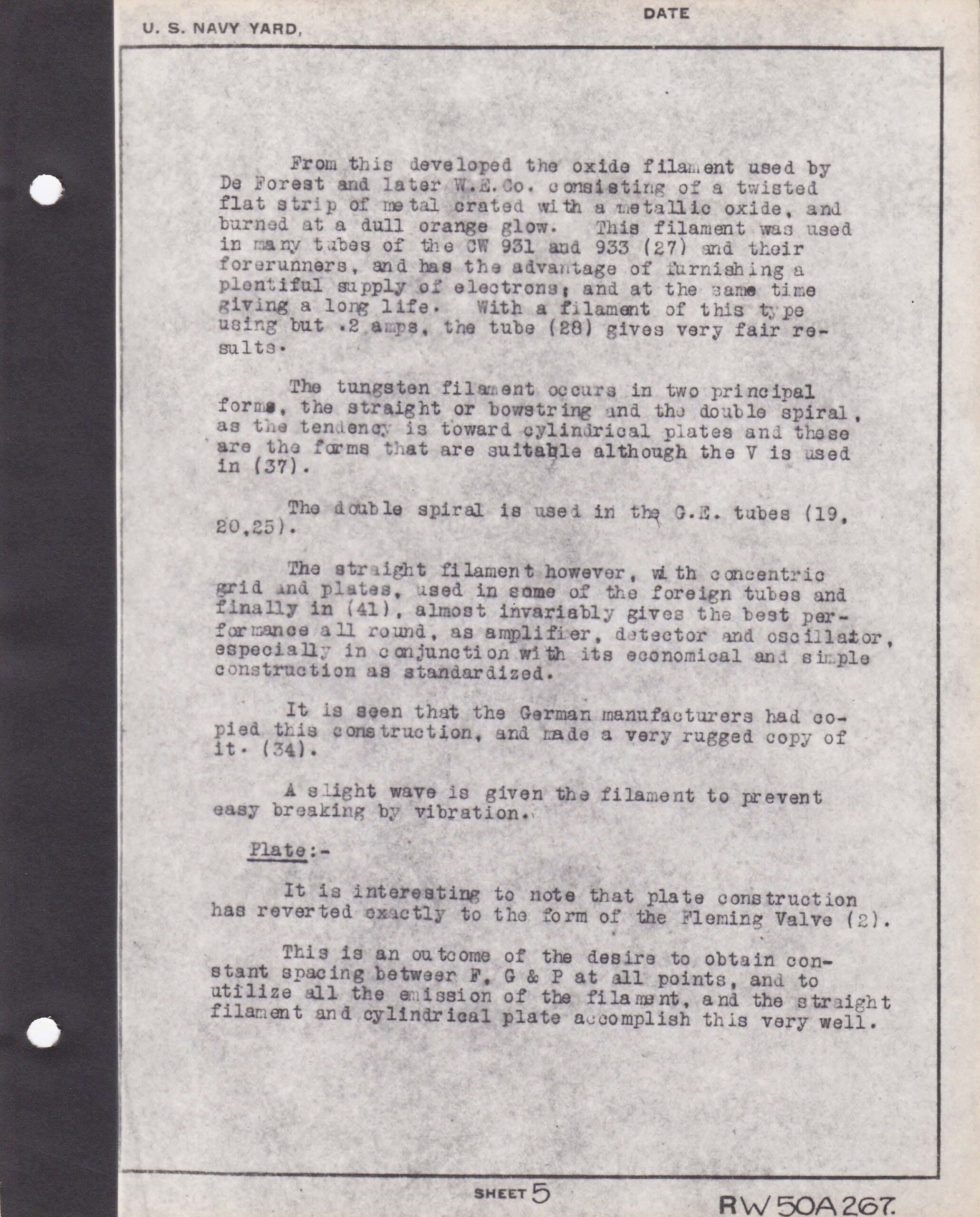
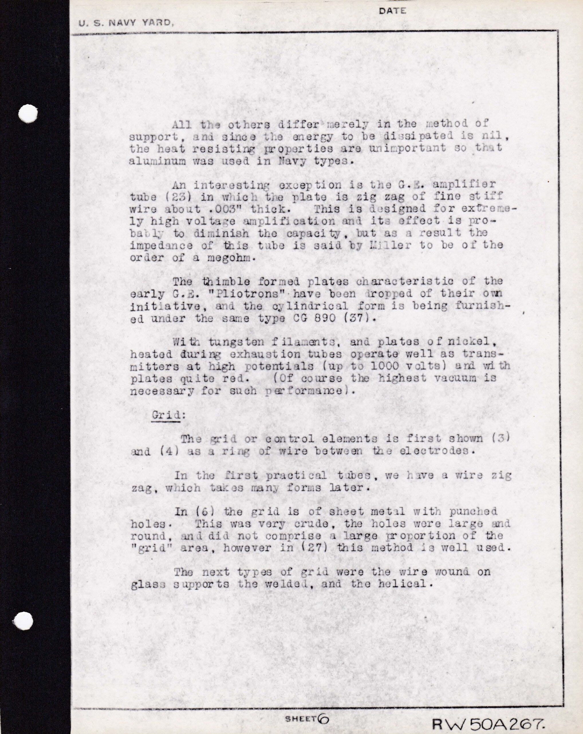
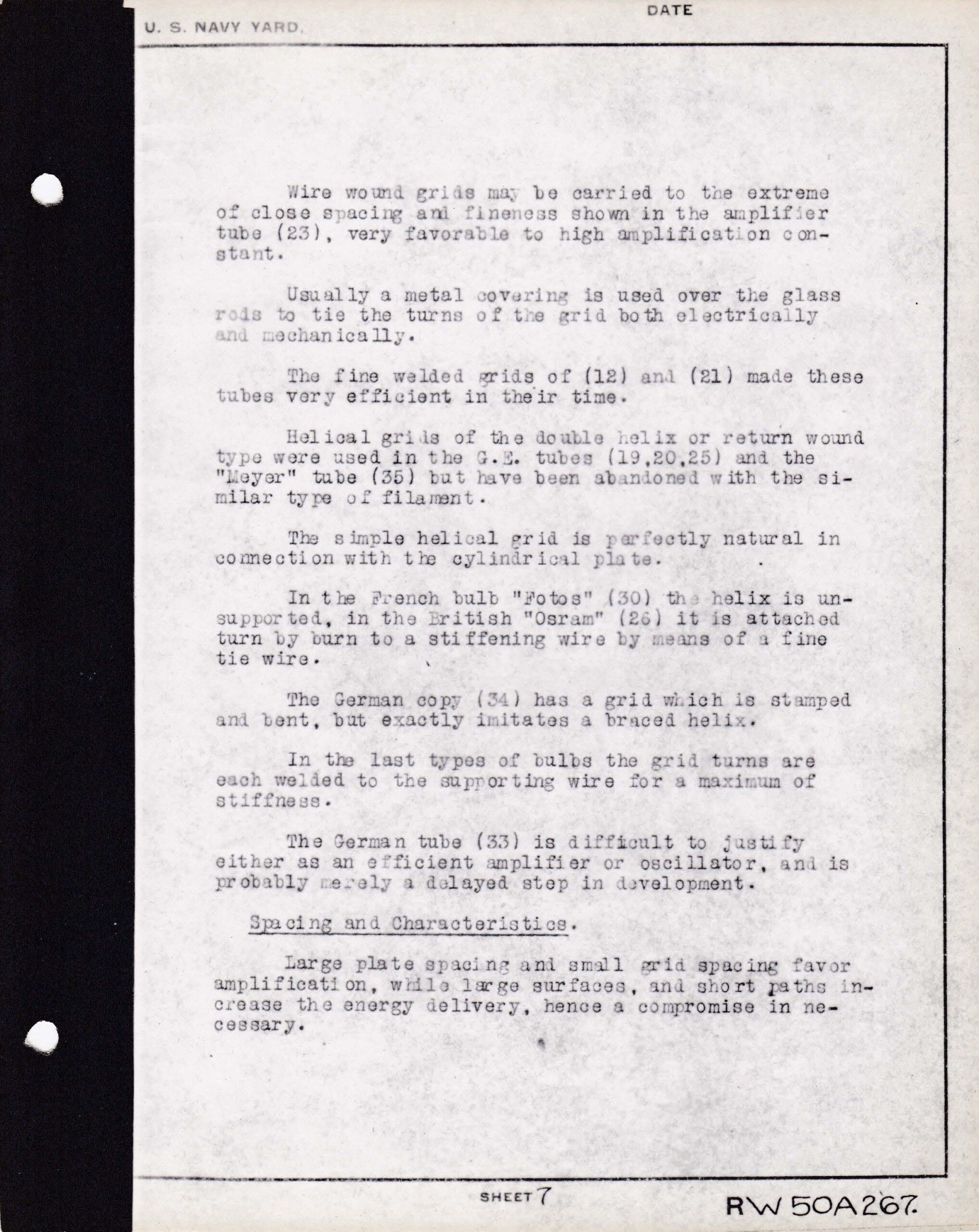
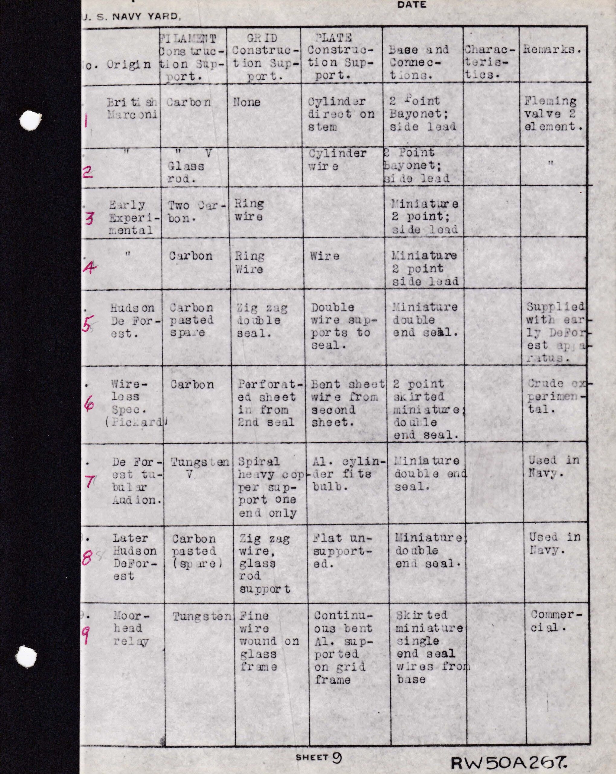
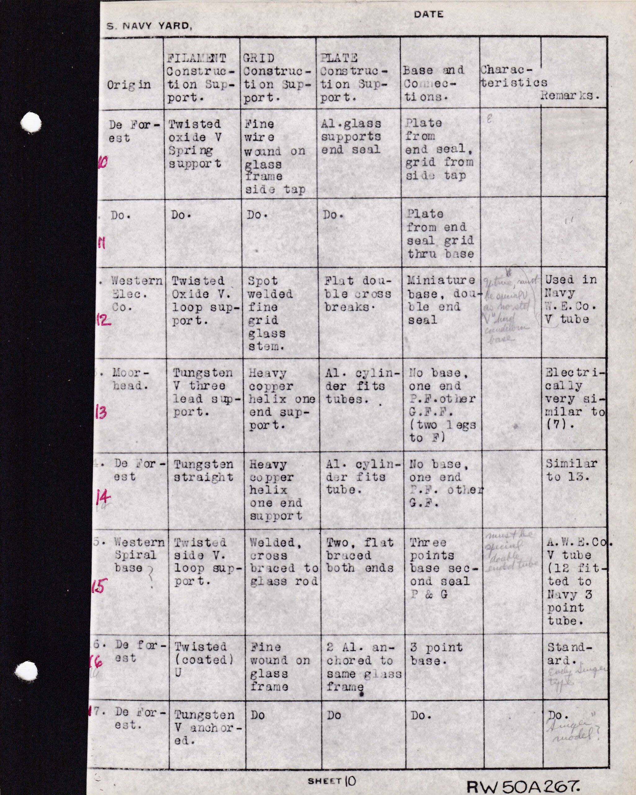
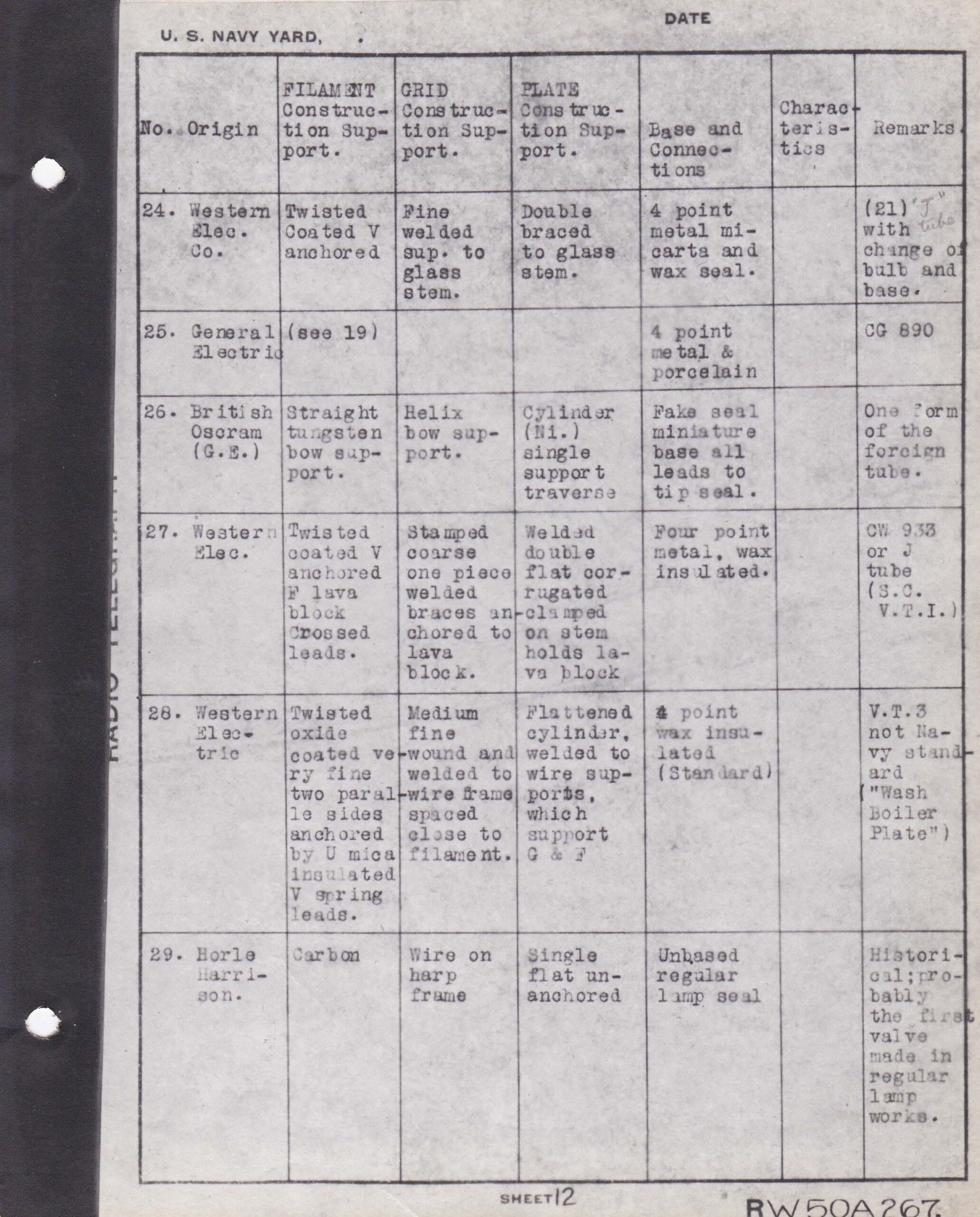
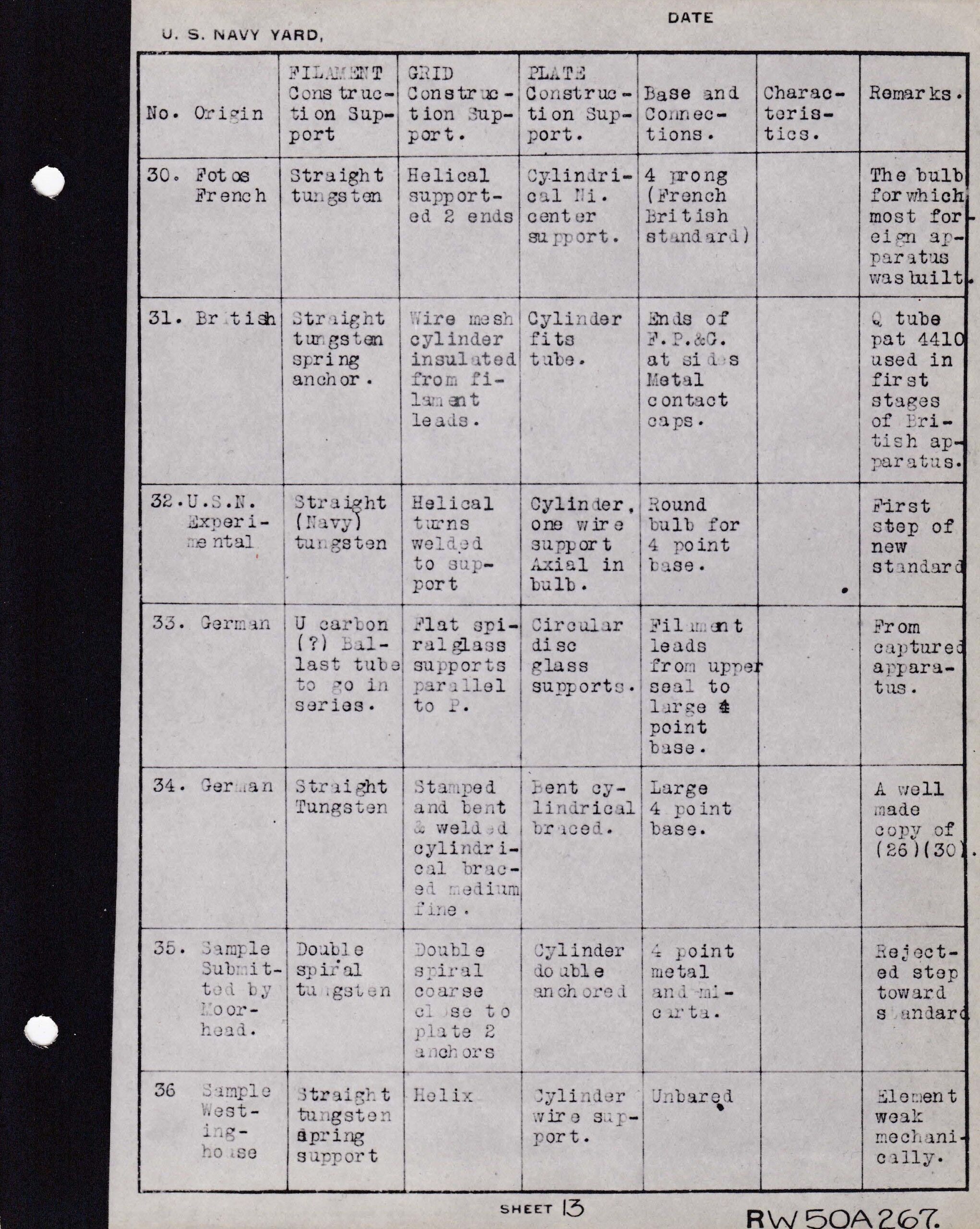
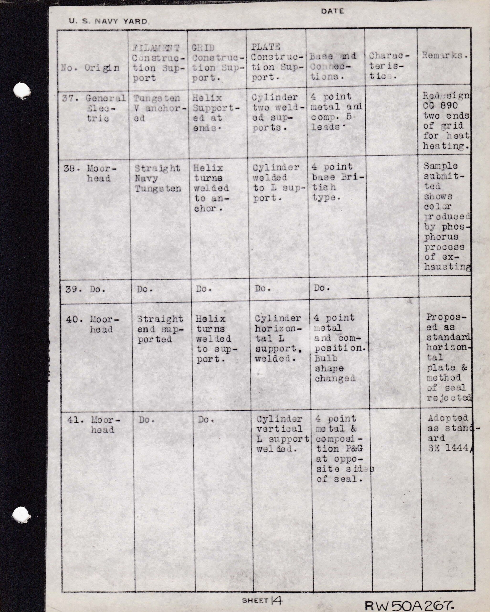
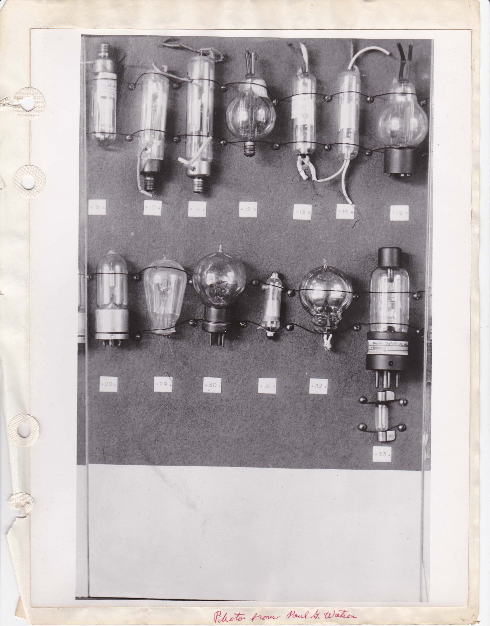
Figs. 6 – 13 The wording in this group of papers were certainly made by Horle explaining the types of tubes included in the photo, again, numbered RW50A267, which seems to help prove this.
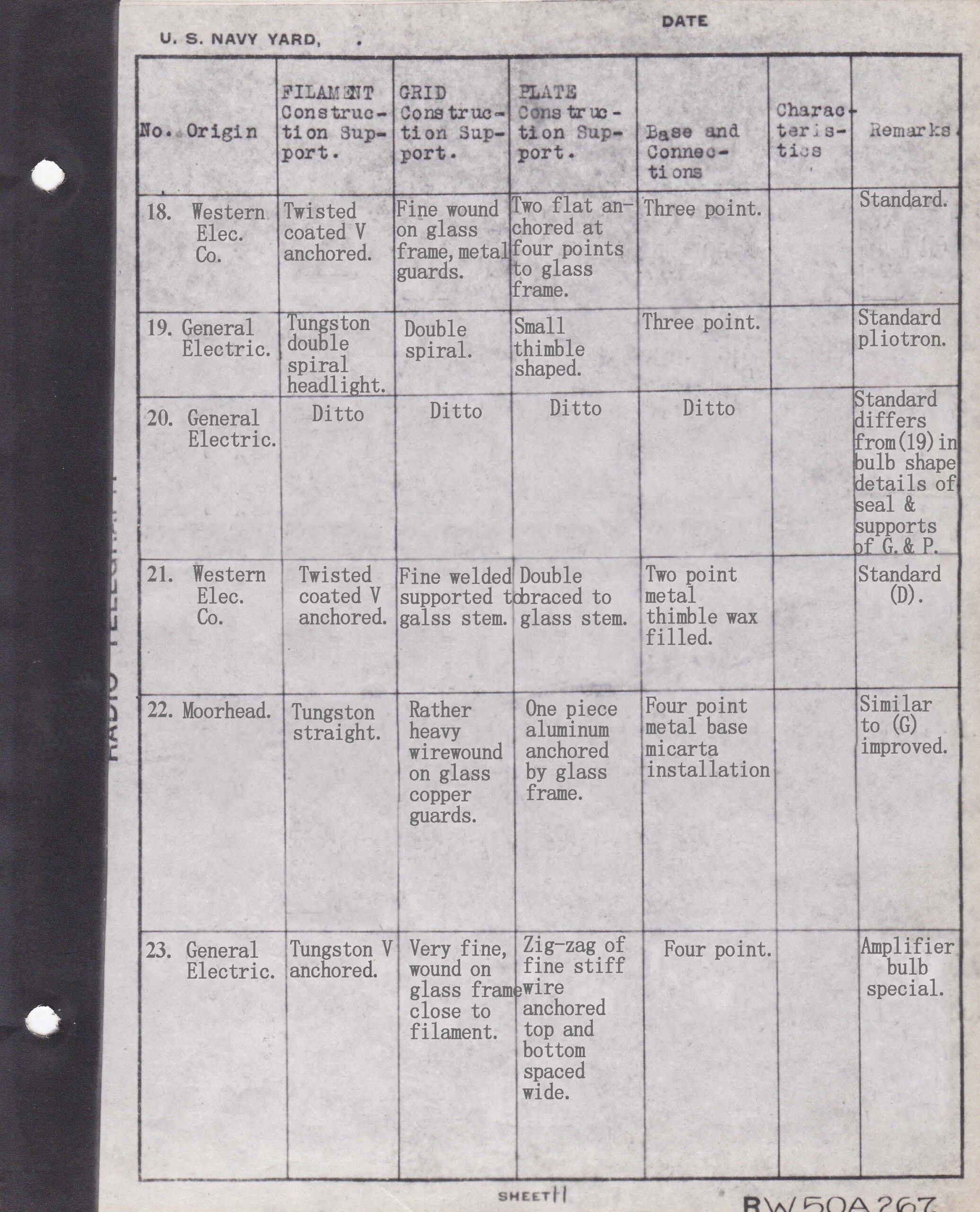
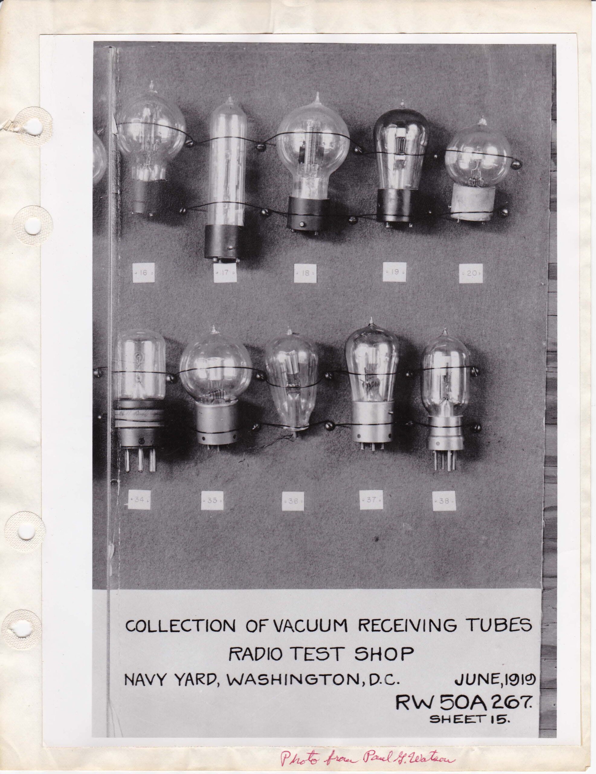
Figs. 14-19 Again, these tube description pages are numbered RW50A267 and this may mean that Horle typed them as well. He may have had help but that is not certain. At the time, the tubes may have been a bit more obscure than they are now which explains the possible mistakes that were made.
Figs. 20 – 23 4 scans of Tynes original pictures he received from Paul G. Watson, a good friend to Tyne. Paul was a US Navy commander, stationed to, I can guess, the US Naval Yard, Washington, DC. Paul was also, it seems, and early collector of radio related items and may be responsible for the Eaton collection being assembled in the first place. He was an early historian of the development of the electron tube. He especially followed the work of De Forest and his invention of the “audion” between 1902-1907. He wrote several articles himself and assembled notes from well-known radio and tube developers of the era. Some of these historical notes include the notes on the 1915 radio transmissions from Arlington, Viriginia to San Francisco and the Eiffel Tower, Paris, conducted by Fessenden and NESCO for the US Navy. His artifacts and written notes are in the Smithsonian for safe keeping. Here we have another tie to the Eaton collection. This author combined the 3 positive photos just for a look.
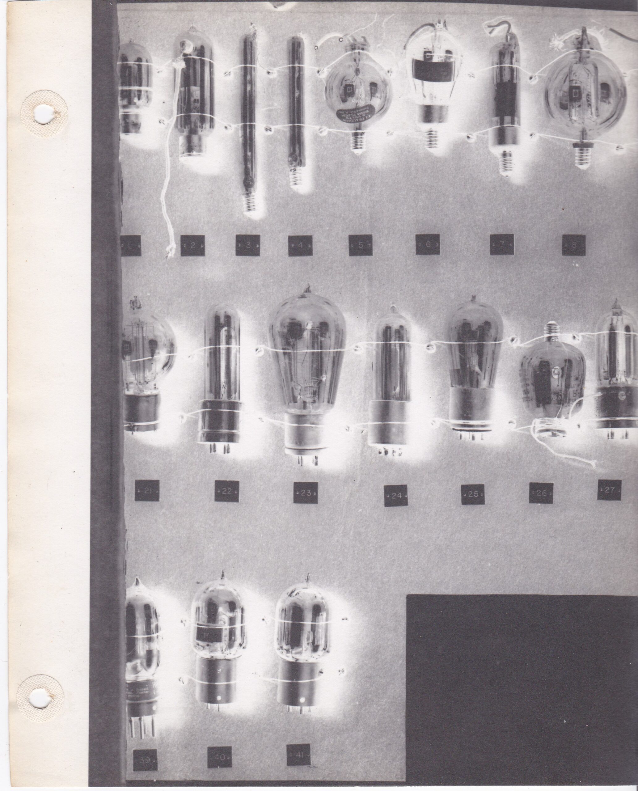
Figs. 24-27 Unless Tyne received these 3 negative photos from Watson, he may have made these at Bell Labs where he worked. I cannot imagine how though? Again, this author combined the 3 negative photos to have fig. 27 all in one photo. Too bad the photo in fig. 24 is cut off at the left.
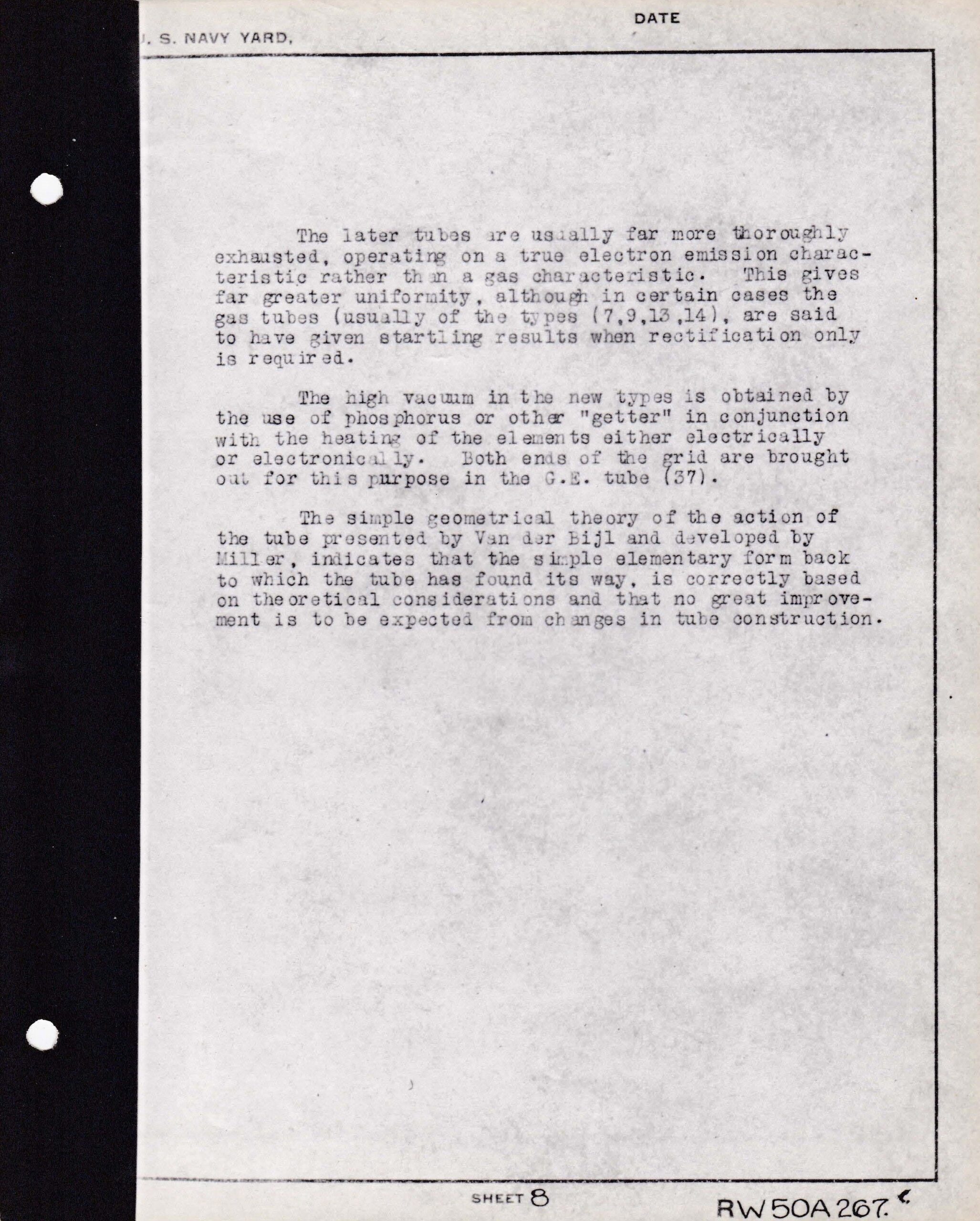
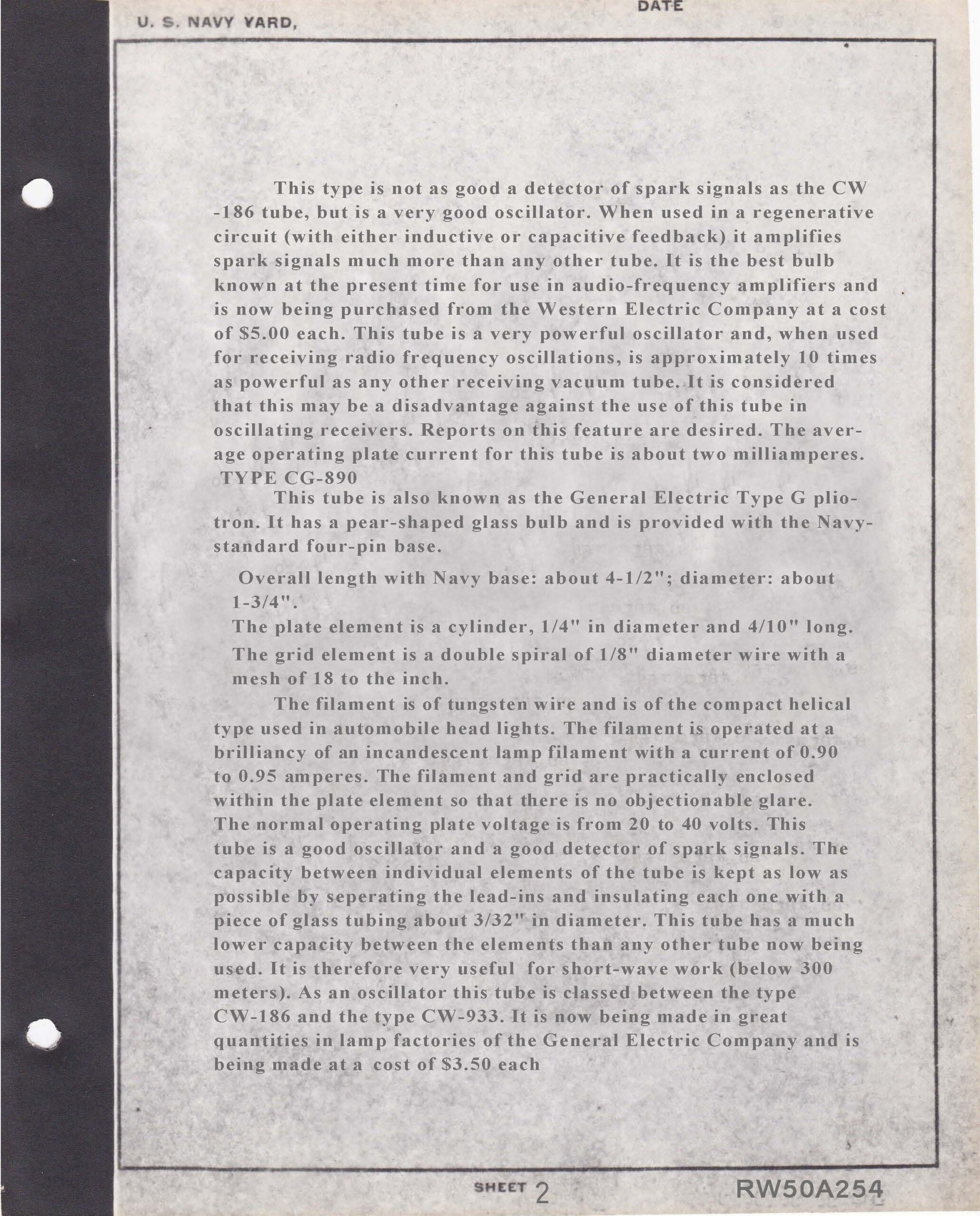
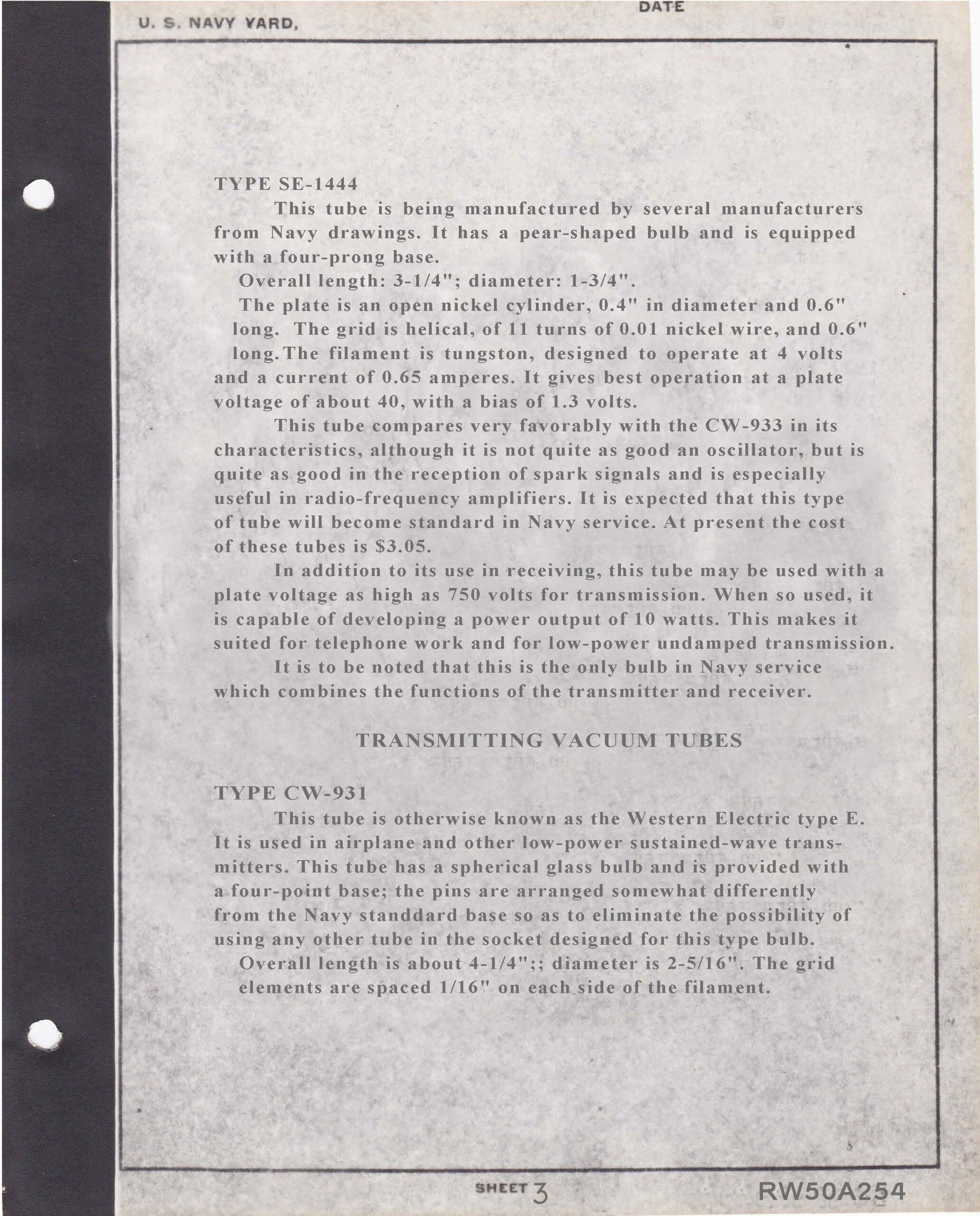
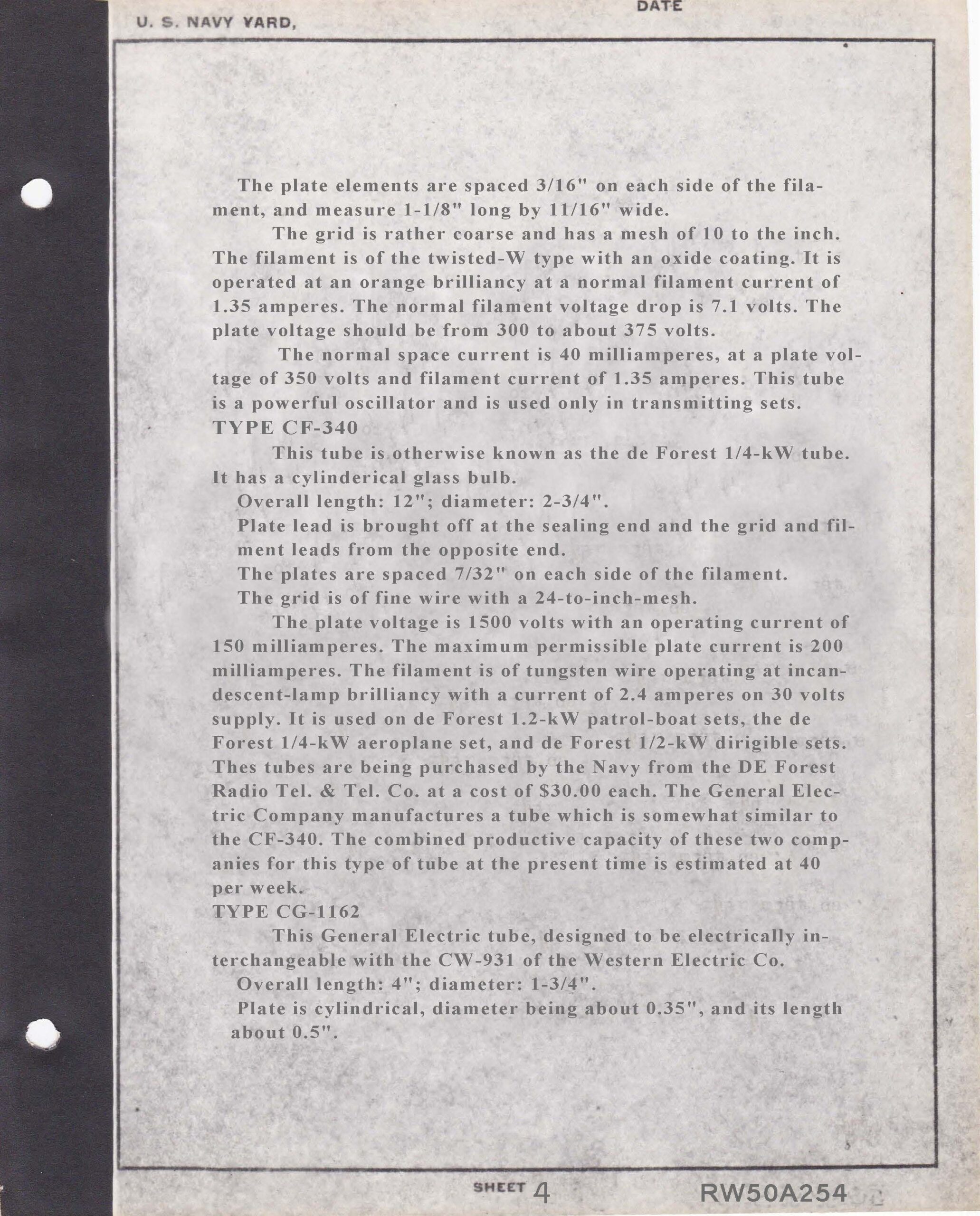
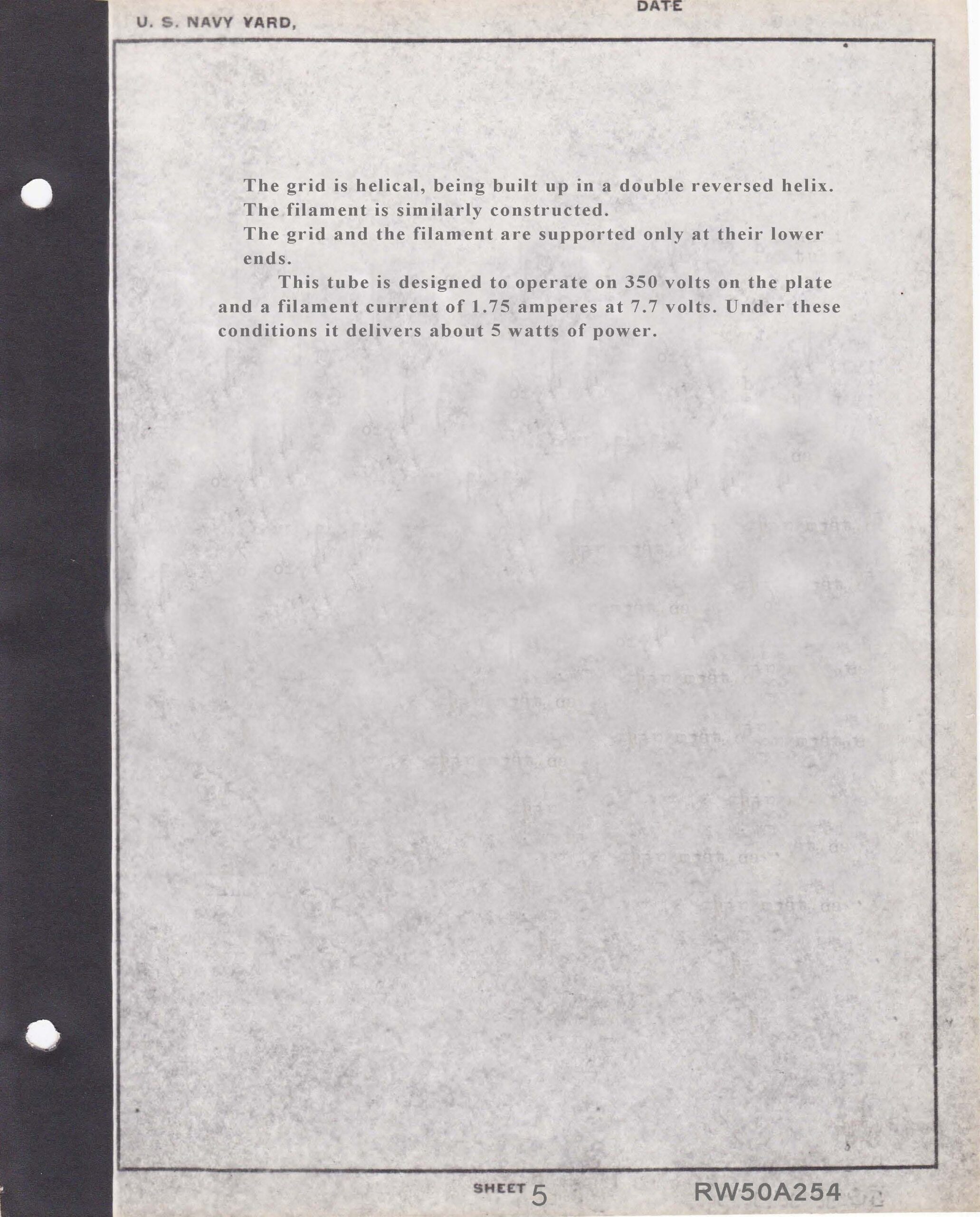
Figs. 28 – 32 This set of documents, apparently, Eaton wrote before Horle wrote his figs. 6 – 13 documents (RW50A267) as they are numbered RW50A254. They describe the types of tubes that were in use by the US Navy at the time of the writing. Quite revealing as to what the Navy thought of each tube they mention.
Figs. 33 – 37 AWA review # 6 contained an article by Lauren Peckham he wrote in 1991 regarding the Eaton collection, starting with page 2. Page 2 has an interesting explanation by Bruce Kelley, AWA founder, of how it came about that he was given the Eaton collection documents by his friend, Edward Duvall. On that same page Lauren begins his key to the photograph or his corrections to the original describer on pages 3-6. Page 1, and pages 7-12 have been left off as they are redundant. Because I left out several pages of the entire Peckham article that appeared in the AWA review# 6, see it here: AWA6
Figs. 38 – 48 AWA review #7 had an article by Jerry Vanicek from 1992. In it, he selected a few of the original descriptions and made corrections. Some conflicted with both the originals and some with Lauren Peckham’s in AWA review #6. This author has tried to do without much success but this will be attempted again for the last parts of this article.
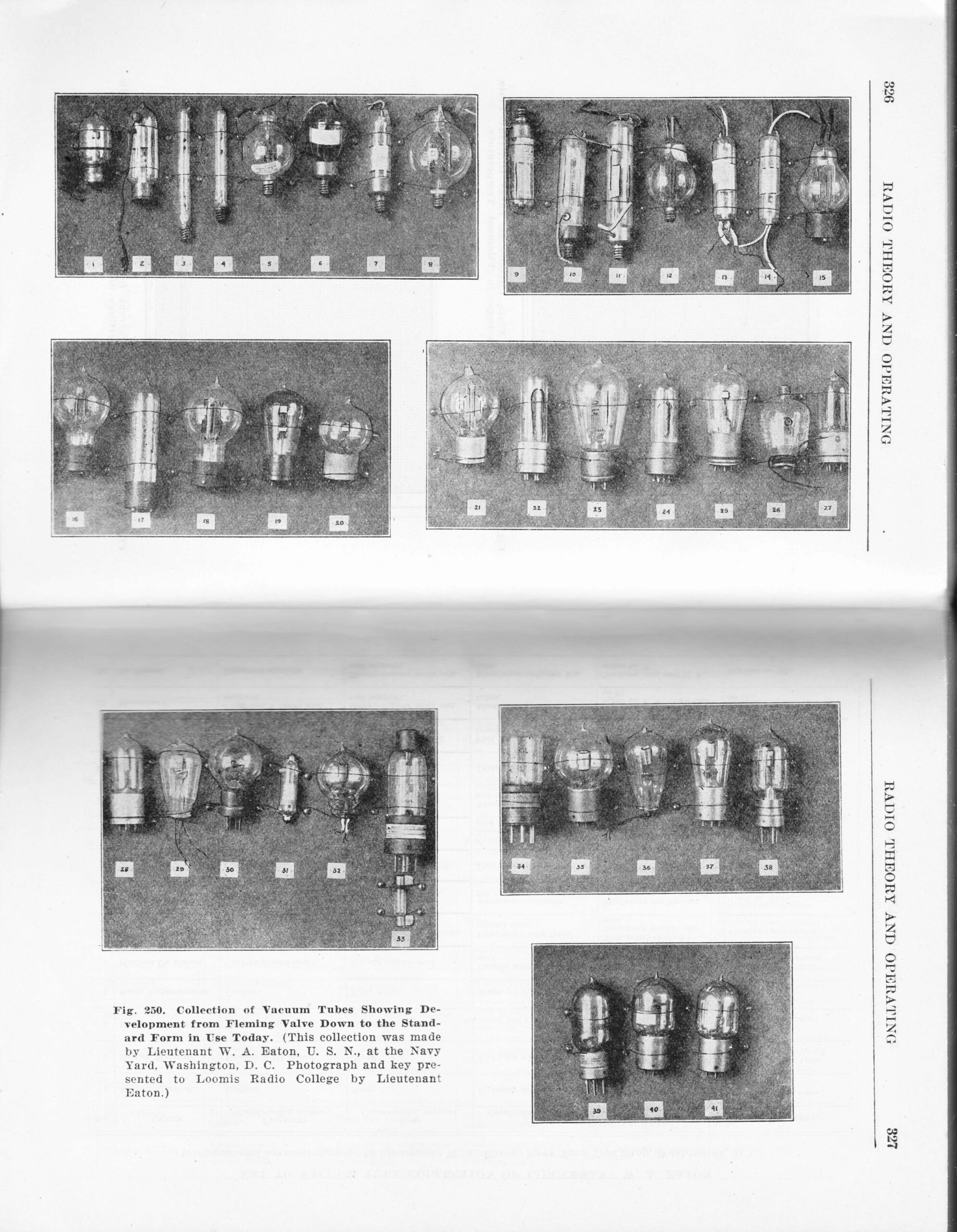
Fig. 49 Mary Texanna Loomis was given a set of pictures from the Eaton collection along with the descriptions. She used this as a teaching tool for her students in her Radio college. The pictures she was given are shown.
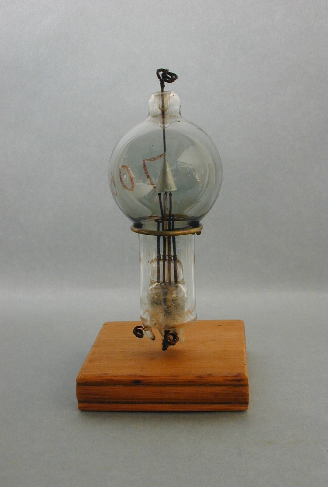
Fig. 50 Shown here is an experimental G. E. pliotron, in the collection of this author, that is the sister of Jerry Vanicek’s pliotron shown in fig. 42. While the pliotron in fig. 42 has a composite base, it is not certain if the tube in fig. 50 ever had one. As can be seen, they both have a conical plate with the wired connection exiting the top, as does the tube in fig. 42. What cannot be seen in the # 50 photo is the number 706 in red grease pencil. This is an ascension number for the William White GE collection in Schenectady, NY. It also has remnants of Tynes numbering system as well but is a bit hard to read. White was the head of G E’s research department from 1912 to 1955 and assembled a fairly large collection of salvaged laboratory samples and from other sources. The pedigree of the tube is: William White, Gerald Tyne, and Jerry Vanicek and was purchased by this author from him. Many tubes from White ended up in the collections of Tyne, Howard Schrader, and Joseph Fetch. Some still reside in the Smithsonian in the White collection.
As a matter of accuracy, Commander Hooper, US Navy also had Eaton material. An article appeared in the Feb., 1920 magazine, Popular Science Monthly in which pictures, leaving out 3, were shown along with the descriptions, again, leaving out 3. Interestingly, the pictures were given to the magazine to be printed by Commander Hooper. It appears he received a set of photos as well? Little better quality but around the same as shown in this article. This author does not know why he received copies.
Below, I will attempt to be as accurate as possible to ID the 41 tubes in the Eaton collection. Comparisons with Peckham, Vanicek, the original describer and this author will be done. To follow along, view figs. 14-19, 33-37 for Lauren, 38-48 for Jerry, and view either the positive or negative Eaton pictures. Click on any hyperlinks below in blue for further examples!
#1. The Horle description is correct. Lauren agrees with Horle but adds it is a 2nd generation Fleming. Jerry states it cannot be a 2nd generation. I agree with Jerry. It’s a 3rd generation at best. Looks like the cylinder plate is mounted directly on press. See this 1911 Marconi catalog showing Fleming valves (#134 R) on page 44 here– MC_1
#2. Jerry does not address this tube. Lauren agrees with Horle and states it is a 2nd gen Fleming and fil. is supported by a glass rod. That seems to be true. I agree it is 2nd gen as it similar to a gallows type with a bayonet base added. I cannot confirm it has a glass support for the fil. but state Horle must have seen it. Same as 132 R in #1 hyperlink.
#3 # & #4. Jerry is silent. I agree with Horle and Lauren, however, they remind me of Weagant valves with candelabra bases applied. More info needed.
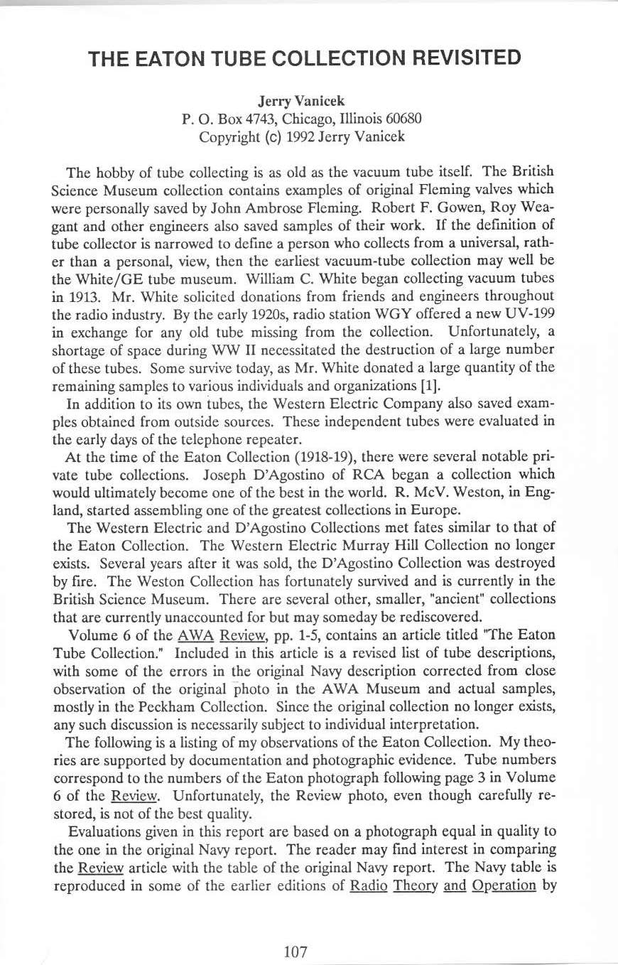
#5. At this point I am finding Lauren agrees with Horle on every tube so I will no longer refer to him. Horle claims the Hudson filament has pasted on tantalum. Jerry states it is a ultra audion with the Hudson wire applied to both filaments and that they are one filament in actuality since they are both connected to the base. That is true. I cannot agree with Jerry or disagree. Jerry owned more than 40 audions, and so he had many ultra audions to look at and apparently none had pasted on tantalum on the filaments. If he states none of his ultra audions have pasted on tantalum, then he must be correct. #5 tube then, is a spherical ultra audion, double plate, double grid, dual filaments, connected to be one. I do own an audion, double plate and grid with one leg wire of the 2nd filament not connected to the base with a Hudson paste applied to both filament tops. It is labeled as a detector, though, not an ultra audion. I think this method of pasting the tantalum was not used long as it tended to fall off after a while. I must agree with Jerry, though, reluctantly.
#6. Jerry did not comment. No doubt here as I agree with the Horle. It is a Pichard Wireless Specialty Apparatus audion. It has the skirted candelabra base for the filament and grid and plate wires out the top.
#7. Horle states this tube is a De Forest tubular audion. Jerry says there is no evidence to support De Forest making such a tube and goes on to say it could be Moorhead made. I think the Horle is correct. Reason 1- All De Forest tubes I have seen have a 90% bend at the end of the vacuum seal off point. Tube 7 has that bend. Horle says the filament is an inverted V and there probably no evidence De Forest made a tubular audion with an inverted V so that is a hang up with Horle. But- Reason 2- Horle also states # 7 was used by the Navy. Moorhead’s tubular ER’s were not used by the Navy. No, Horle is correct here.
#8. Again, Horle states the filament is the pasted tantalum Hudson type. That is very unlikely. Hudson tantalum wrapped wire on the filament, yes, pasted, no. Jerry is correct here in that tube 8 is a later glass arbor type double grid and plate supported in the usual manner spherical audion. I will add in looking at the negative photo that the grid and plate are much longer than usual and while I cannot see the length of the filaments in the photo, they may be longer as well.
#9. Horle’s description is correct but incomplete, Jerry is silent. No doubt this is a Moorhead series D electron relay with a skirted candelabra base. Much like the De Forest CF 185 but the plate on the D is continuous as it wraps around the top of the tube. Story: Years ago, I sold Bill Condon my un-based series D, He was not happy with this so he purchased a skirted candelabra base from Jerry. It ends of the bulb would not fit into the skirt, but was close. He spent months using fine sandpaper to reduce the size of the bulb. It worked but later he lifted the tube by the glass and it broke at the spot he was sanding. He may have purchased another or perhaps he took the picture that is on his website before it broke. Never found out which.
#10. Again, Horle is correct but incomplete in that he was not familiar with the De Forest CF 185 in Navel use. Lauren points this out the fact that it is a CF 185 in his account. Jerry is silent. I agree with Lauren in all respects in that it is an early version of the 185. Lauren thinks the grid is exiting the glass bulb but I cannot see the plate. It may have broken off the top?
#11. Horle is correct. Lauren is correct. Jerry does not address this tube. I agree all that is stated.
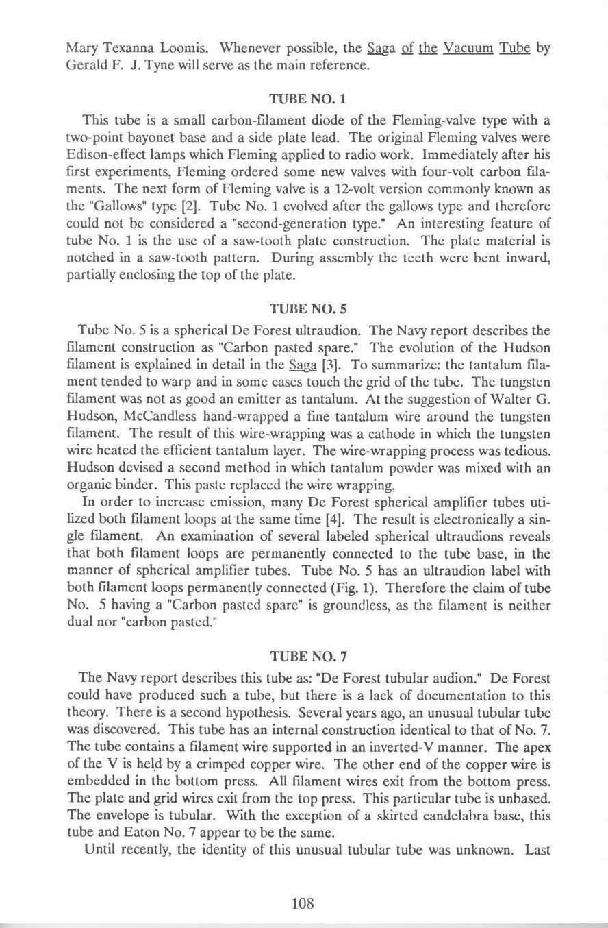
#12. Horle is correct. Lauren and Jerry disagree on which version, WE V or M, predates the other. I am silent on this matter but what Jerry states seems logical. Tyne wrote his own note stating this must be a special V because no WE V tube had a candelabra base.
#13. Horle is correct. Seems to be a normal Moorhead tubular Electron Relay. The common filament wire is on the 2 wire end and the 2 wires for the V filament are on the opposite end and are connected separately on the 3 wire end.
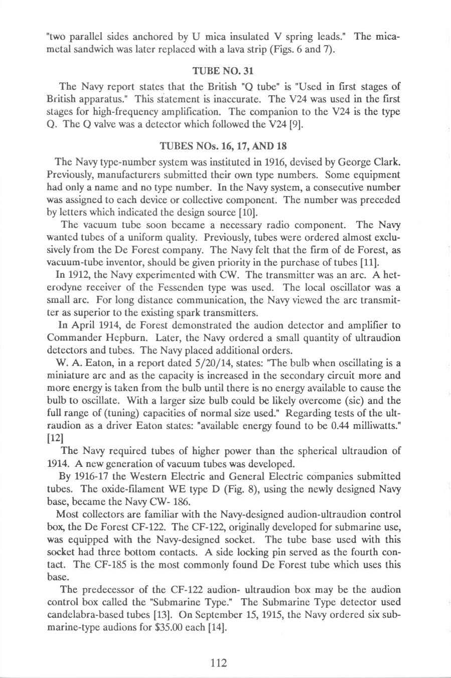
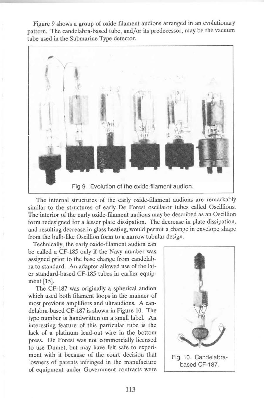
#14. Horle is correct. Jerry is silent. This is a De Forest tubular audion, 1 filament, 2 wires out each end with no special characteristics. May have DF pressed on the plate?
#15. Horle is correct. Jerry is silent. Lauren agrees with Horle but adds: the Navy preferred the 3 point base to candelabra for ease of replacement. I agree with both but I am perplexed at why 2 more wires, grid & plate, exit the top. Tyne wrote notes for this tube as well stating: must be special WE double ended tube? Yes, why?
#16. Horle is correct in that it is a De Forest product. Jerry silent. Lauren states it is an early CF 185 and that may be true If it is true, I have never seen a spherical CF 185 so if I add “experimental”, I could agree. Tyne adds a note: “early singer type” in pencil. I do not think so. The 3 point base means that the side pin makes a connection as well, and have a fiber base to keep the side pin insulated from that base as in all CF 185’s. This makes sense and if it makes sense, it is true.
#17. Horle is correct again. Lauren adds it is a tubular CF 185. I agree as I have seen early tubular examples of the CF 185. Again, 3 point base, side pin making a connection and a fiber base. Tyne adds a written note “singer model”?. I don’t know why Tyne would say that? but I am not Tyne.
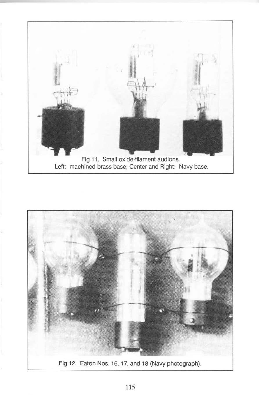
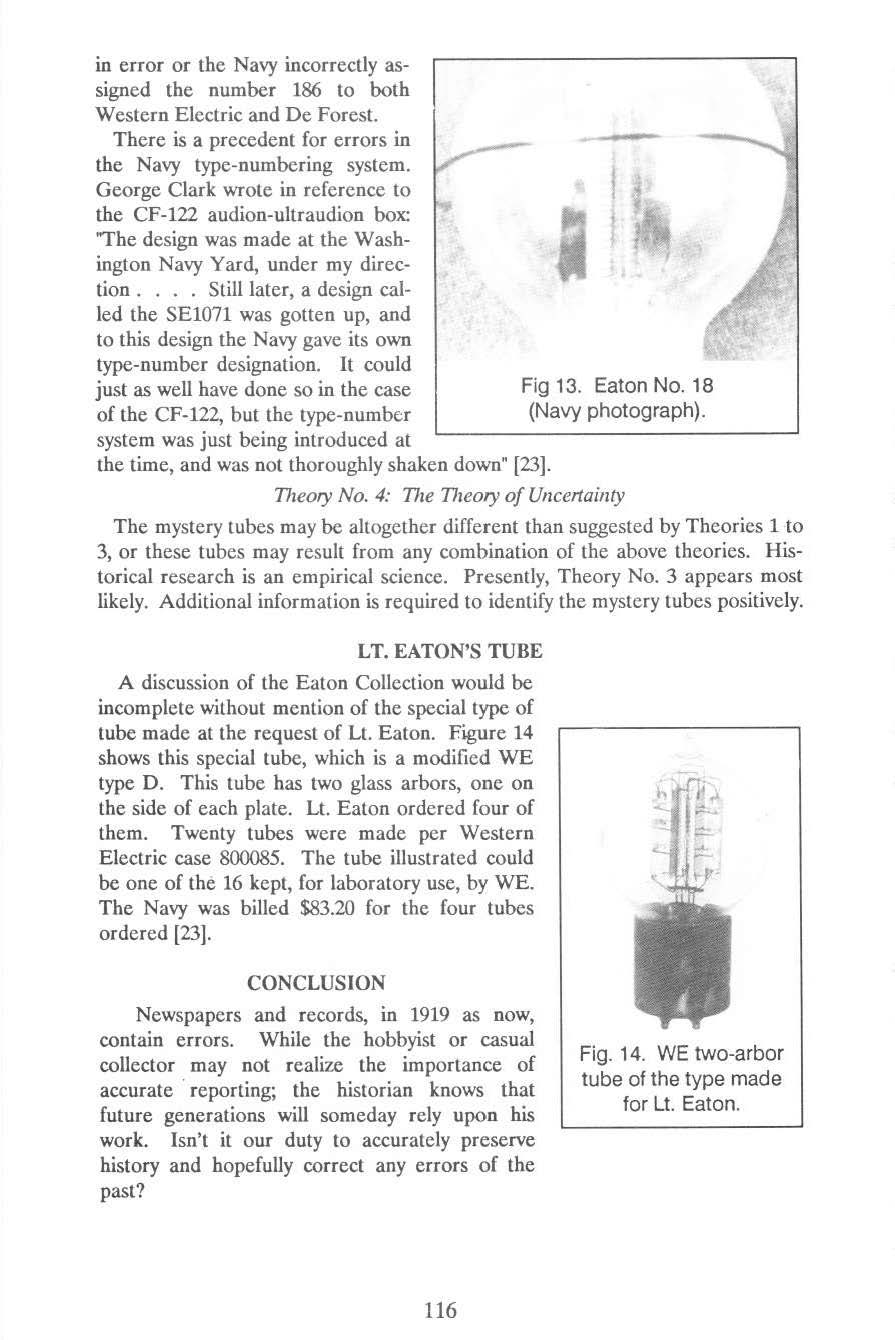
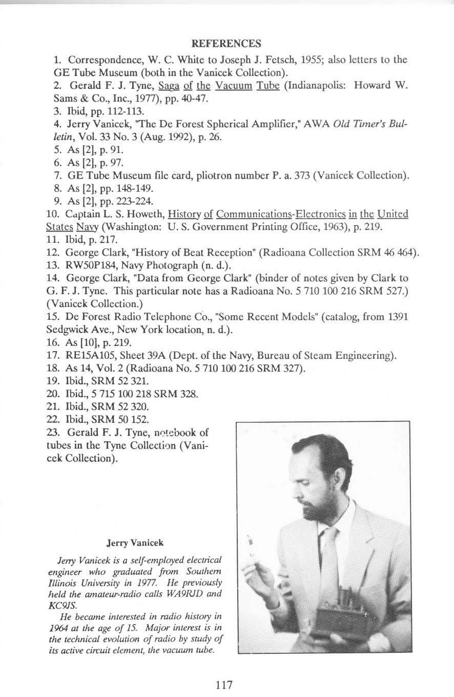
#18. Horle is incorrect. Lauren points this out but it is easy to see. This is another spherical CF 185 but perhaps a newer design. Same as 16 & 17 with 3 point base, fiber base, side pin connection, etc.
Jerry devoted 5 pages in his report on the Eaton numbered tubes 16, 17, and 18. This report must be read to understand why Jerry waited until the end of his entire article to comment on these numbered tubes. He considered them to be a mystery and that they needed a close look. Please read them carefully.
#19. Horle is correct but incomplete. Horle should have been able to ID this tube as a GE CG 886. Lauren agrees but parts of his description are incorrect as to the shape of the plate. No doubt a GE CG 886, 3 point base and side pin makes a connection. It was a standard Navy tube. The plate is cup shaped, not thimble shaped. The side pin and one of the 3 pins below are the filament ends.
Click on the 5 blue hyperlinks below to view the pictures I have added.
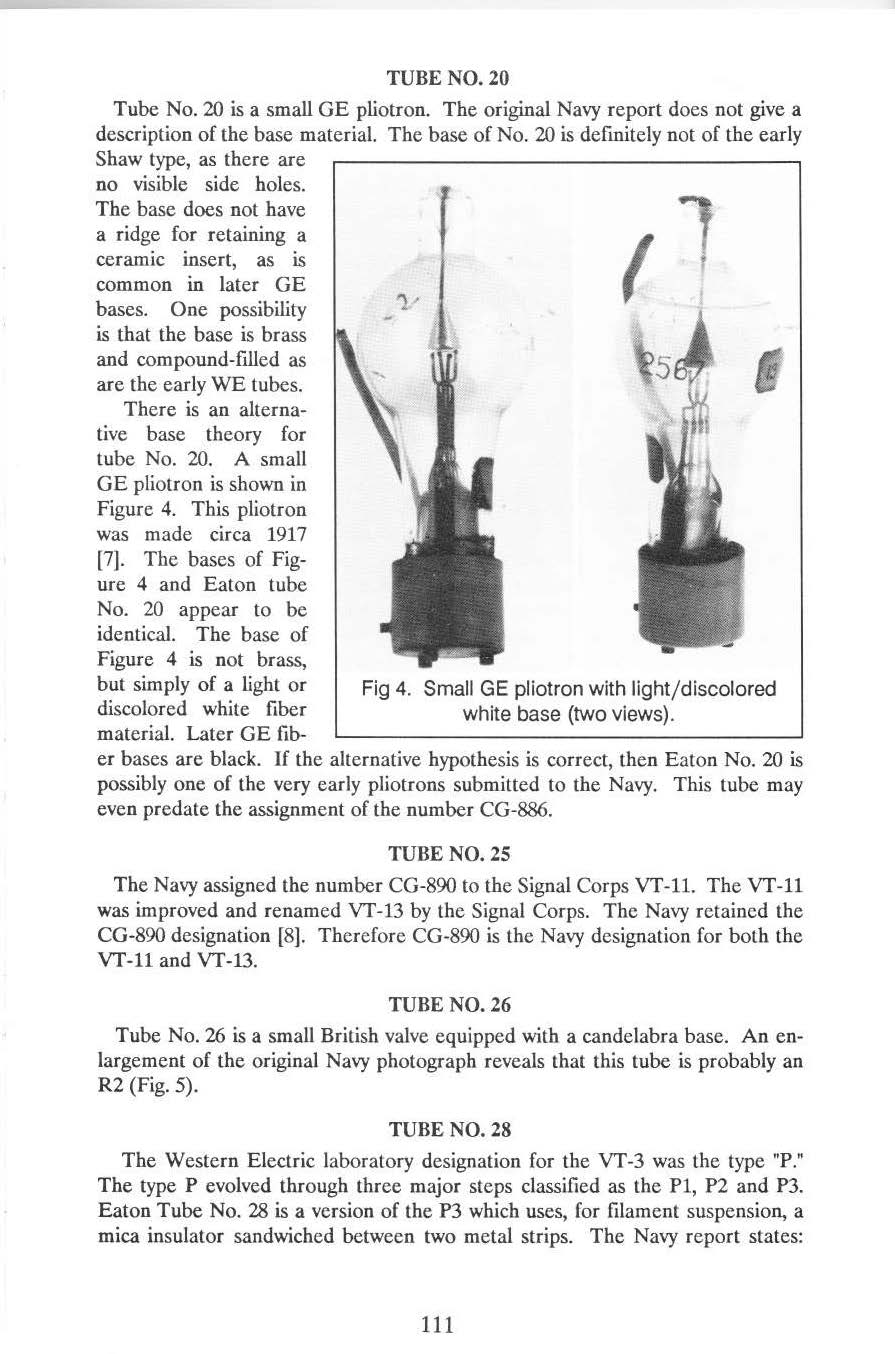
#20. Horle is correct but incomplete again. Lauren is incorrect or less than complete. I can see why they had trouble as this tube is a GE laboratory sample that led to the early CG Pliotron designs. I agree with Jerry. My description of #20: GE made laboratory samples for the Navy as this is one from the Vanicek collection. Picture here: V_1. Here is a picture of Pliotron Lab sample #1 from the National Lamp Works book: “National in the World War”. here: LS_1. As can be seen, lab sample #1 does differ from the Jerry’s example in the it has 2 supports of the cup plate. Minor but different. They both differ from Eaton tube #20 in that the Eaton # 20, the cup plate is supported from above, clearly rather than from below, and it may have a glass arbor as well. Eaton tube #20 has a white composite base like Jerry’s picture #4 in his article and the reason he included that picture. Here is a better picture of the same one in Fig. 4 from the article here: V_2. V_2, in Jerry’s collection has a white composition base, 3 point base like Eaton 20, but differs in the plate shape, etc. The wire out the base is one leg of the filament. Keep in mind that the tubes were made by different divisions of GE. Extremely interesting tubes.
#21. Horle and Lauren are exactly correct. No disagreement what so ever. I can only add that all structures are supported from the press and from above with a glass arbor, 3 point base with the side pin having a connection, and probably has gold tipped pins.
#22. Horle is correct but failed to ID this tube as a Moorhead series D. Lauren is correct in that it is a series D with a 4 pin standard base. I agree with all.
#23. Horle is correct but could have known it was a GE CA pliotron that may have been made after 1919. Jerry- silent. Lauren is absolutely correct in that it is a GE CA pliotron but failed to state in a much different glass bulb. Other than that fact, I agree. here is an earlier version of the CA here: LS_2 from the GE book, “National in the World War”.
#24. Horle is correct but incomplete. Jerry-silent. Lauren is correct and I agree with him. This is the type J, an early version of the WE VT-1, with an earlier than mostly seen brass 4 pin base. It features a glass arbor for added top support. One version I have has the gold tipped 4 pin brass base and VT-1 pressed in the base. Another has the normal WE nickel base that has VT-1 pressed on the base. Tyne has a pencil note on this tube that confirms it is a type J. Good enough for me.
#25. Horle gives a perfect description of this tube as the CG 890 was well known. Jerry gives a broader description that is perfect. Lauren is correct also, but again, the plate is not “thimble-shaped” but is cup shaped. I agree, generally but can add this: I have several of these types made by the National Lamp Works division of GE but- I have never seen a CG 890 without little arms sticking out from the bottom of the cup to support it, the support arms in Eaton 25 do not have those arms but the support wires attach directly to the side of the cup. I have seen the Army version of the CG 890, the VT 11 that looks identical to Eaton 25. They may exist but I have not seen one. I would suggest that Eaton tube 25 is an Army version of the CG890, the VT-11. I will also add that how the cups were supported of if they had a cup shape at all changed quite frequently. This could be the subject of my next article. Very interesting!
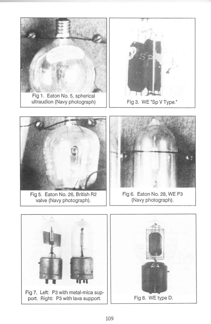
#26. Horle is correct but would have had a hard time knowing British tubes very well. Jerry states it is probably a British Osram R2. Lauren claims it is an R4 and that it is a single ended tube. This is incorrect. All wires exit the opposite end of the candelabra base. The 2 filament wires wrap around the outside of the glass bulb. One attaches to the screw base and the other is insulated to the center post of the base. The grip and plate wires must be attached separately from the candelabra base; therefore, it is a double ended tube. I agree with Jerry as I blew up the positive and negative photos and it is definitely an R2. I may add that both the R2 and R4 were used extensively by the British Navy.
#27. Horle is correct. Lauren is correct in all he states. Jerry is silent. I agree with Horle and Lauren exactly.
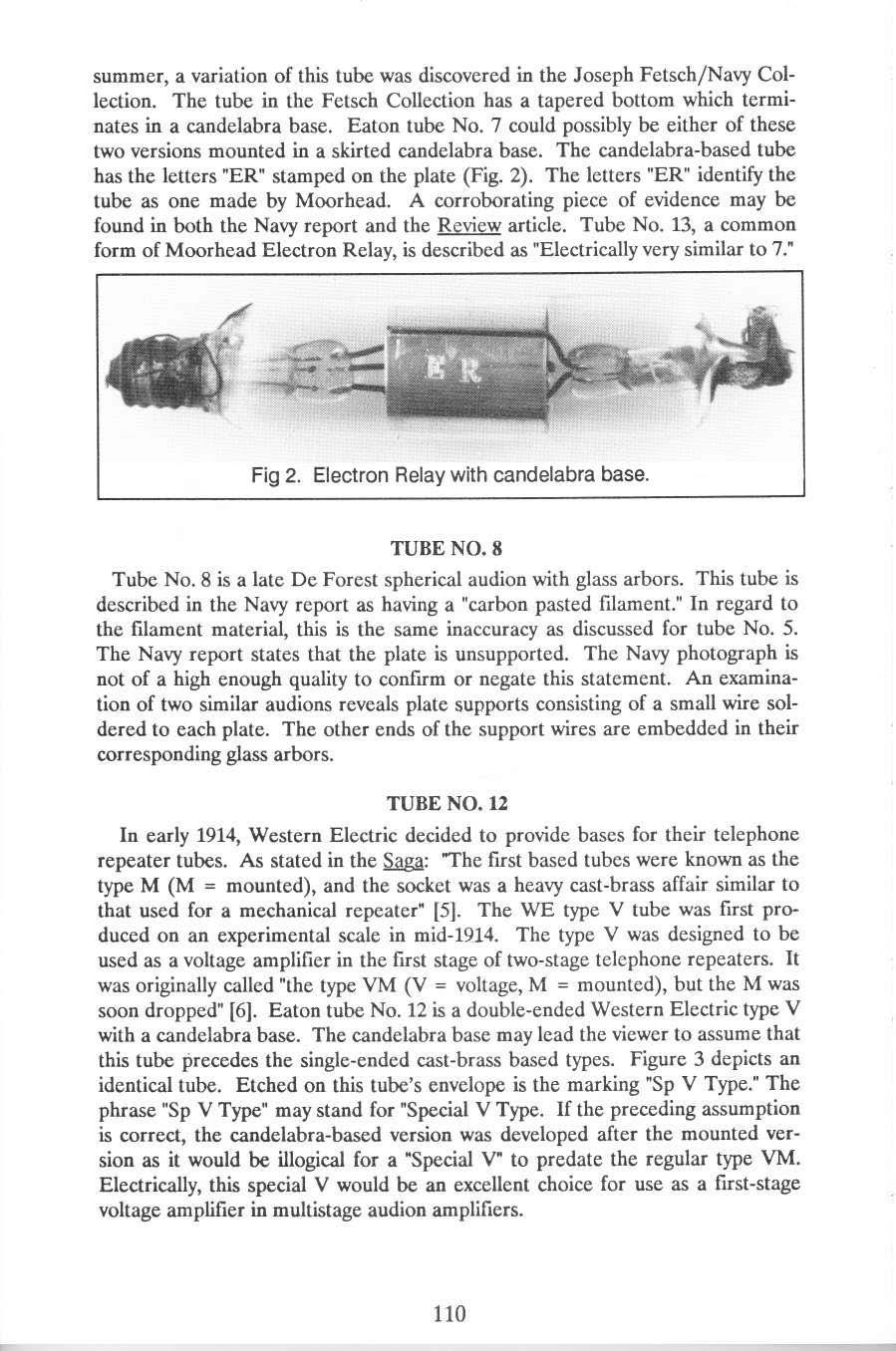
#28. Horle, Jerry and Lauren all seem to be correct but Jerry gave many more details. Without having an example myself, I cannot speak to this tube. Very Rare.
#29. Cannot speak to the correctness of Horle or Lauren. I assume they are talking about the Edison light bulb plant in Harrison, New Jersey after it was taken over by GE. This would mean that Eaton 29 was the first attempt at a vacuum tube by GE and be extremely rare indeed.
#30. Jerry is silent. Cannot state if Horle or Lauren are correct as I cannot see Fotos Grammont either on a paper tag or etching on the bulb. I can confirm it is a French TM that could have been made by several companies. I will add that it is true that the TM became the European standard but the manner in which heating the inner structures during the evacuation process became a standard in the US as well. See my article on the French TM called “Vacuum Tubes of WW1- France-Britian- US” here on vacuumtubearchive.com
#31. I do not have much knowledge about this type of British Q tube but according to Jerry, Horle is incorrect about what the Q valve was used for so I submit to his opinion.
#32. I am not certain what Horle meant on this tube as he describes it as a US Navy experimental. Does this mean the Navy made it or that Moorhead submitted it as his experimental tube? At first look, it could be either? Jerry is silent and Lauren just repeats what Horle has stated. Looking closely at this tube tells me it is a bit out of the norm for a Moorhead made tube. The plate seems a little smaller, the spiral grid is at least 2-1/2 turns above the plate, and the support wire for the upper filament is short and must angle up to reach above the grid. Moorhead would not have submitted this tube with that flaw. However, the flattened end of the support that the filament is welded to is as Moorhead would have done. A mystery there? Horle states the filament is straight Navy tungsten. Moorhead made all his filaments in a zig-zag manner so this supports a Navy made tube. The fact that it is spherical and unbased but the lower glass is made to have a base cemented in is a mystery and would not have been submitted by Moorhead? If the Navy had made a few up for testing, a base would not have been necessary. I must believe Horle when he states it is a SE 1444 but it is nearly impossible to tell a SE 1444 from any other Moorhead tube. My conclusion: Moorhead submitted his SE 1444 to the Navy. It was promising enough for the Navy to make a few of their own for testing purposes. The fact that it is spherical supports this theory as Moorhead never made his SE 1444’s spherical. The Navy testing resulted in producing a set of specs, specs that Moorhead needed to start his production. Again, if it makes sense then it is most likely true. As it turned out, the Moorhead SE 1444 was a very successful design and was the only tube in Navy use at the time, that could be used as an amplifier and detector. The Eaton # 32 tube was extremely rare and interesting, to put it mildly.
#33. Horle did a good job describing what he was seeing considering it was a 2 part captured tube. Jerry is silent. Lauren gives his specific knowledge as EVN 94. I cannot comment for lack of knowledge.
#34. Again, Horle is good, Jerry is silent and Lauren has knowledge enough to state it is an EVE 173. I have no knowledge of this tube.
#35. Horle states it was had a double filament and was a rejected step towards standard, but for what spec tube? Jerry is silent and Lauren repeats Horle’s description. Moorhead stepped well beyond his normal internal structure designs with this tube with a double filament. Rejected for a reason I do not understand as it seems to be a well- designed tube?
#36. Lauren seems to know more about this tube than most collectors so I will submit to him.
#37. Horle & Lauren are exactly correct. This is a re-design of the CG 890, or VT 11 & VT 13. Confusing, yes. The Navy continued to use CG 890 even when it was re-designed as Eaton 37. The Army, using the very same re-designed tube as the CG 890, changed the name VT 11 to VT 13. In my collection I have the very same looking tubes, one is etched with CG 890 and the other does not say CG 890 so it is a VT 13. GE and the users of the tubes in the Navy and Army could be confused so GE inked all the presses with the # 20. This was meant to state all were interchangeable.
#38. Horle does not, but Lauren does state correctly the fact this is a Moorhead VT 32. No doubt about this. Moorhead made the VT 32 transmitting tube as a replacement to the British B transmitting valve. It is electrically the same as the Moorhead type B transmitter with a different shaped glass bulb and came with the British standard 4 pin base. The press was split at the point where the plate wire passes through to help dissipate the heat from the voltage necessary for operation. There seems to be some confusion with collectors as to what the 32 was made to be, a transmitter or receiving tube. I am certain it was made to be a transmitter to replace the British B transmitting valve. So far, I have only found that Bill Condon’s website describes the VT 32 correctly, and that includes many museums and collectors. The Eaton # 38 tube has the color to indicate the use of phosphorus but they were made without and have a clear glass bulb. Moorhead designed and released the 32 so late into WW1 that not many, if any were shipped to Britain.
#39. Horle states this is another Moorhead VT 32 and Lauren agrees but adds that it could be a type C. I doubt that it is a type C. The 32 has a horizontal structure where the type C has a vertical, and the C has a US standard base. There is not enough information to state with certainty. I can only add that this example has the paper label still attached. I cannot quite make out the wording but wish I could as this is the only paper label seen on a 32.
#40. Horle states this tube has a horizontal structure and Lauren agrees. I cannot read the paper tag, so to speculate, it is a Moorhead VT 32 transmitter with a new bulb shape and US standard 4 pin base, perhaps for ease of testing.
#41. Horle and Lauren agree that Eaton 41 is a standard Moorhead SE 1444. I agree, this is the SE 1444 that became the Moorhead standard. Electrically, it is not a VT 32 but a newly named Marconi VT.
To be clear, I mean no disrespect to those who attempted to correctly describe the Eaton collection. In fact, I applaud anyone who has ever tried as it is a difficult task at best! Furthermore, while trying my best, I am as vulnerable as anyone and make my share of mistakes. In my title, I end that title with “last word”. By that I mean my last word. I encourage others to have another look too.
I received 5 pictures regarding the Eaton Collection that are in the AWA library from Felicia & Jim Kruezer. View them here: https://vacuumtubearchive.com/wp-content/uploads/2025/09/5_ps.pdf
Sources:
- “Saga of the Vacuum Tube, Gerald Tyne, 1977
- “AWA Review # 6”, portions of articles by George Clark, “Story of the Tube Collection of the Washington Navy Yard”, portions of article by Bruce Kelley, “The Eaton Collection and AWA”, article by Lauren Peckham, “Key to the Photograph”, article by L. C. F. Horle, “Vacuum Receiving Tubes – Report on Collection of Various Types”. Permission granted by AWA.
- “AWA Review #7”, portions of article by Jerry Vanicek, “The Eaton Tube Collection Revisited”. Permission granted by AWA.
- Eaton tube collection photos and text, Clark, Tyne, and Vanicek collections.
- Hyperlinks to photos V_1 & V_2 in the text above were taken by this author that were in the Vanicek collection.
- Hyperlinks to photos LS_1 & LS_2 from the book “National in the World War”, General Electric. These pertain to the hyperlinks in the text above.
- Hyperlink to catalog MC_1, “Marconi Receiving and Measuring Instruments”, Marconi’s Wireless Telegraph Company, resides in the Gruber collection.
- Picture of tube in Fig. # 50, Experimental Pliotron Tube. Pedigree: William White, Tyne, Vanicek, resides in the Gruber collection.
- “Radio Theory and Operating”, Mary Texanna Loomis, 1927. Book in my collection.
Leave a Reply